- 您现在的位置:买卖IC网 > PDF目录11131 > MAX4534EUD+T (Maxim Integrated Products)IC MULTIPLEXER 4X1 14TSSOP PDF资料下载
参数资料
| 型号: | MAX4534EUD+T |
| 厂商: | Maxim Integrated Products |
| 文件页数: | 2/14页 |
| 文件大小: | 0K |
| 描述: | IC MULTIPLEXER 4X1 14TSSOP |
| 产品培训模块: | Lead (SnPb) Finish for COTS Obsolescence Mitigation Program |
| 标准包装: | 2,500 |
| 功能: | 多路复用器 |
| 电路: | 1 x 4:1 |
| 导通状态电阻: | 400 欧姆 |
| 电压电源: | 单/双电源 |
| 电压 - 电源,单路/双路(±): | 9 V ~ 36 V,±4.5 V ~ 20 V |
| 工作温度: | -40°C ~ 85°C |
| 安装类型: | 表面贴装 |
| 封装/外壳: | 14-TSSOP(0.173",4.40mm 宽) |
| 供应商设备封装: | 14-TSSOP |
| 包装: | 带卷 (TR) |
MAX4534/MAX4535
NO_ Input Voltage
The maximum allowable input voltage for safe opera-
tion depends on whether supplies are on or off and on
the load configuration at the COM output. If COM is
referred to a voltage other than ground, but within the
supplies, VNO_ may range higher or lower than the
supplies, provided the absolute value of VNO_ -
VCOM_ is less than 40V. For example, if the load is
referred to +10V at COM_, then the NO_ voltage range
can be from +50V to -30V. As another example, if the
load is connected to -10V at COM_, the NO_ voltage
range is limited to -50V to +30V.
If the supplies are ±15V and COM is referenced to
ground through a load, the maximum NO_ voltage is
±36V. If the supplies are off and the COM output is ref-
erenced to ground, the maximum NO_ voltage is ±40V.
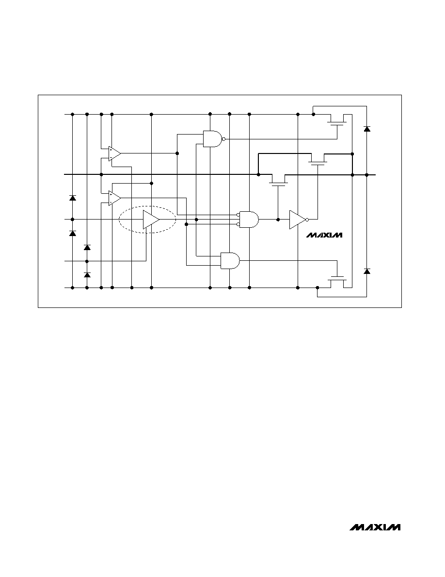
Normal Operation
Two comparators continuously compare the voltage on
the NO_ pin with V+ and V- supply voltages. When the
signal on NO_ is between V+ and V-, the multiplexer
behaves normally, with FETs N1 and P1 turning on and
off in response to A_ signals (Figure 1). The parallel
combination of N1 and P1 forms a low-value resistor
between NO_ and COM_ so that signals pass equally
well in either direction.
Positive Fault Condition
When the signal on NO_ exceeds V+ by about 150mV,
the positive fault comparator output goes high, turning
off FETs N1 and P1 (Figure 1). This makes the NO_ pin
high impedance regardless of the switch state. If the
switch state is “off,” all FETs turn off, and both NO_ and
COM_ are high impedance. If the switch state is “on,”
FET P2 turns on, clamping COM_ to V+.
Negative Fault Condition
When the signal on NO_ goes about 150mV below V-,
the negative fault comparator output goes high, turning
off FETs N1 and P1 (Figure 1). This makes the NO pin
high impedance regardless of the switch state. If the
switch state is “off,” all FETs turn off, and both NO_ and
COM_ are high impedance. If the switch state is “on,”
FET N2 turns on, clamping COM_ to V-.
Fault-Protected, High-Voltage,
Single 4-to-1/Dual 2-to-1 Multiplexers
10
______________________________________________________________________________________
NORMALLY OPEN SWITCH CONSTRUCTION
COM_
P2
MAX4534
MAX4535
P1
N1
ON
LOW
FAULT
HIGH
FAULT
V+
NO_
A_
GND
ESD DIODE
V-
N2
Figure 1. Functional Diagram
相关PDF资料 |
PDF描述 |
|---|---|
| MAX4535EUD+T | IC MULTIPLEXER DUAL 2X1 14TSSOP |
| UPD78F1211MC-GAA-AX | MCU 16BIT 78K0R/LX3 38-SSOP |
| UPD78F1203MC-CAB-AX | MCU 16BIT 78K0R/LX3 30-SSOP |
| MAX4678EUE+T | IC SWITCH QUAD SPST 16TSSOP |
| MAX4677EUE+T | IC SWITCH QUAD SPST 16TSSOP |
相关代理商/技术参数 |
参数描述 |
|---|---|
| MAX4535CPD | 功能描述:多路器开关 IC RoHS:否 制造商:Texas Instruments 通道数量:1 开关数量:4 开启电阻(最大值):7 Ohms 开启时间(最大值): 关闭时间(最大值): 传播延迟时间:0.25 ns 工作电源电压:2.3 V to 3.6 V 工作电源电流: 最大工作温度:+ 85 C 安装风格:SMD/SMT 封装 / 箱体:UQFN-16 |
| MAX4535CPD+ | 功能描述:多路器开关 IC 2:1 1Ch/4:1 2Ch MUX RoHS:否 制造商:Texas Instruments 通道数量:1 开关数量:4 开启电阻(最大值):7 Ohms 开启时间(最大值): 关闭时间(最大值): 传播延迟时间:0.25 ns 工作电源电压:2.3 V to 3.6 V 工作电源电流: 最大工作温度:+ 85 C 安装风格:SMD/SMT 封装 / 箱体:UQFN-16 |
| MAX4535CSD | 功能描述:多路器开关 IC RoHS:否 制造商:Texas Instruments 通道数量:1 开关数量:4 开启电阻(最大值):7 Ohms 开启时间(最大值): 关闭时间(最大值): 传播延迟时间:0.25 ns 工作电源电压:2.3 V to 3.6 V 工作电源电流: 最大工作温度:+ 85 C 安装风格:SMD/SMT 封装 / 箱体:UQFN-16 |
| MAX4535CSD-T | 功能描述:多路器开关 IC RoHS:否 制造商:Texas Instruments 通道数量:1 开关数量:4 开启电阻(最大值):7 Ohms 开启时间(最大值): 关闭时间(最大值): 传播延迟时间:0.25 ns 工作电源电压:2.3 V to 3.6 V 工作电源电流: 最大工作温度:+ 85 C 安装风格:SMD/SMT 封装 / 箱体:UQFN-16 |
| MAX4535CUD | 功能描述:多路器开关 IC RoHS:否 制造商:Texas Instruments 通道数量:1 开关数量:4 开启电阻(最大值):7 Ohms 开启时间(最大值): 关闭时间(最大值): 传播延迟时间:0.25 ns 工作电源电压:2.3 V to 3.6 V 工作电源电流: 最大工作温度:+ 85 C 安装风格:SMD/SMT 封装 / 箱体:UQFN-16 |
发布紧急采购,3分钟左右您将得到回复。