- 您现在的位置:买卖IC网 > PDF目录1943 > MAX4818ETE+T (Maxim Integrated Products)IC SWITCH DUAL SPDT 16TQFN PDF资料下载
参数资料
| 型号: | MAX4818ETE+T |
| 厂商: | Maxim Integrated Products |
| 文件页数: | 4/21页 |
| 文件大小: | 0K |
| 描述: | IC SWITCH DUAL SPDT 16TQFN |
| 产品培训模块: | Lead (SnPb) Finish for COTS Obsolescence Mitigation Program |
| 标准包装: | 2,500 |
| 功能: | 开关 |
| 电路: | 2 x SPDT |
| 导通状态电阻: | 5 欧姆 |
| 电压电源: | 单/双电源 |
| 电压 - 电源,单路/双路(±): | 6 V ~ 11 V,±3.3 V ~ 5 V |
| 电流 - 电源: | 800nA |
| 工作温度: | -40°C ~ 85°C |
| 安装类型: | 表面贴装 |
| 封装/外壳: | 16-WQFN 裸露焊盘 |
| 供应商设备封装: | 16-TQFN-EP(5x5) |
| 包装: | 带卷 (TR) |
MAX4818/MAX4819
High-Bandwidth T1/E1 Dual-SPDT Switches/
4:1 Muxes
12
______________________________________________________________________________________
Fault Protection
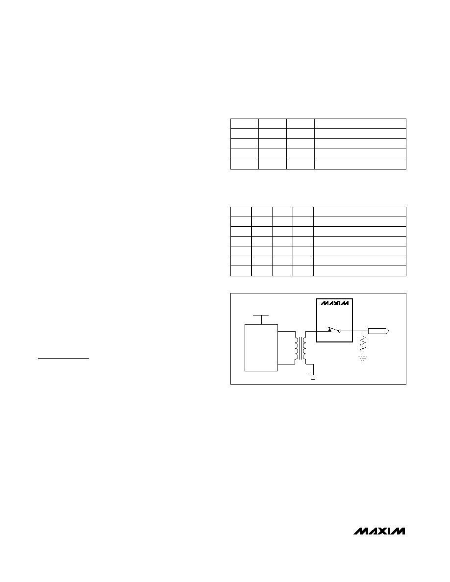
The fault protection of the MAX4818/MAX4819 allows
the devices to handle input signals of more than twice
the supply voltage without clamping the signal, latching
up, or disturbing other cards in the system. The device
detects when the input voltage drops below the nega-
tive supply. As soon as a fault condition is detected,
the switch is immediately turned off for 128 clock
cycles (typically 128s). At the end of the 128s time-
out, the switch is turned back on for one clock cycle. At
the end of the one clock cycle, if the signal is within the
operating range, the switch will remain on. Otherwise,
the device will turn the switch off again for 128 clock
cycles. This will repeat until the signal is within the
operating range. In T1/E1 redundancy applications, this
can happen when the load resistor (RL) is removed or
disconnected for any reason, as shown in Figure 1.
Without a load resistor, the output voltage when using a
1:2 transformer can be as high as ±11V.
Hot Insertion
The MAX4818/MAX4819 tolerate hot insertions, thus
are not damaged when inserted into a live backplane.
Competing devices can exhibit low impedance when
plugged into a live backplane that can cause high
power dissipation leading to damage of the device
itself. The MAX4818/MAX4819 have relatively high
input impedance when V+ and V- supplies are uncon-
nected or connected to GND. Therefore, the devices
are not destroyed by a hot insertion. In order to guar-
rantee data integrity, the V+ and V- supplies must be
properly biased.
Applications Information
T1/E1 N+1 Redundancy
Figures 6, 7, and 8 show a basic architecture for twisted-
pair interface (120
, E1 or 100, T1). Coaxial cable inter-
face (75
, E1) can be illustrated with the same figures
but without the single-ended to differential conversion
stage. A single protection card can replace up to
N line cards in a N+1 redundancy scheme. Figure 6
shows the switches sitting in the line cards where they
can reroute any of the input/output signals to a protection
line card. Figure 7 shows a “multiplexed” redundancy
architecture using the MAX4819 where the multiplexers
are in the line cards. This architecture is more scalable as
the number of boards is increased. It also does not
require a dedicated external switching card as the multi-
plexers reside in the line cards themselves. The number
of signals routed through the backplane is substantially
higher than in the switching-card architecture. Figure 8
shows a similar architecture, but the multiplexers reside in
the protection switching card. These figures do not show
the surge-protection elements and resistors for line termi-
nation/impedance matching.
MAX4818
MAX4819
5V
±10%
LIU
Tx
TRING
TTIP
10V
±10%
1:2
+
-
Vo
RL
NO
COM
Figure 1. Fault Protection
EN
SET
IN_
COM_ CONNECTION
0X
X
NONE
10
0
NC_
10
1
NO_
11X
NO_
Table 1. Dual SPDT Truth Table
(MAX4818)
(X = don’t care.)
EN
SET
A1
A0
COM CONNECTION
0X
XX
NONE
10
00
NO1
10
01
NO2
10
NO3
10
11
NO4
11
XX
NO1, NO2, NO3, NO4
Table 2. 4:1 Multiplexer Truth Table
(MAX4819)
(X = don’t care.)
相关PDF资料 |
PDF描述 |
|---|---|
| MAX4831ELT+T | IC SWITCH 1X1 6UTDFN |
| MAX483ECSA | IC TXRX RS485/RS422 LOWPWR 8SOIC |
| MAX4842AEXT+T | IC CTLR OVP 4.7V SC70-6 |
| MAX4850ETE+ | IC SWITCH DUAL SPDT 16TQFN |
| MAX4854HETE+ | IC SWITCH DUAL SPDT 16TQFN |
相关代理商/技术参数 |
参数描述 |
|---|---|
| MAX4818EUE | 功能描述:多路器开关 IC RoHS:否 制造商:Texas Instruments 通道数量:1 开关数量:4 开启电阻(最大值):7 Ohms 开启时间(最大值): 关闭时间(最大值): 传播延迟时间:0.25 ns 工作电源电压:2.3 V to 3.6 V 工作电源电流: 最大工作温度:+ 85 C 安装风格:SMD/SMT 封装 / 箱体:UQFN-16 |
| MAX4818EUE+ | 功能描述:多路器开关 IC RoHS:否 制造商:Texas Instruments 通道数量:1 开关数量:4 开启电阻(最大值):7 Ohms 开启时间(最大值): 关闭时间(最大值): 传播延迟时间:0.25 ns 工作电源电压:2.3 V to 3.6 V 工作电源电流: 最大工作温度:+ 85 C 安装风格:SMD/SMT 封装 / 箱体:UQFN-16 |
| MAX4819ETE | 功能描述:多路器开关 IC RoHS:否 制造商:Texas Instruments 通道数量:1 开关数量:4 开启电阻(最大值):7 Ohms 开启时间(最大值): 关闭时间(最大值): 传播延迟时间:0.25 ns 工作电源电压:2.3 V to 3.6 V 工作电源电流: 最大工作温度:+ 85 C 安装风格:SMD/SMT 封装 / 箱体:UQFN-16 |
| MAX4819ETE+ | 功能描述:多路器开关 IC RoHS:否 制造商:Texas Instruments 通道数量:1 开关数量:4 开启电阻(最大值):7 Ohms 开启时间(最大值): 关闭时间(最大值): 传播延迟时间:0.25 ns 工作电源电压:2.3 V to 3.6 V 工作电源电流: 最大工作温度:+ 85 C 安装风格:SMD/SMT 封装 / 箱体:UQFN-16 |
| MAX4819ETE-T | 制造商:Maxim Integrated Products 功能描述:HIGH-BANDWIDTH T1/E1 DUAL-SPDT SWIT - Tape and Reel |
发布紧急采购,3分钟左右您将得到回复。