- 您现在的位置:买卖IC网 > PDF目录1228 > MAX4989EVKIT+ (Maxim Integrated Products)EVALUATION KIT FOR MAX4989 PDF资料下载
参数资料
| 型号: | MAX4989EVKIT+ |
| 厂商: | Maxim Integrated Products |
| 文件页数: | 2/9页 |
| 文件大小: | 0K |
| 描述: | EVALUATION KIT FOR MAX4989 |
| 产品培训模块: | Lead (SnPb) Finish for COTS Obsolescence Mitigation Program |
| 标准包装: | 1 |
| 主要目的: | 接口,交叉点开关/多路复用器 |
| 嵌入式: | 否 |
| 已用 IC / 零件: | MAX4989 |
| 主要属性: | 双向 4 选 2 USB 2.0 交点开关 |
| 次要属性: | 2.7 V ~ 5.5 V 电源 |
| 已供物品: | 板 |
�� �
�
�MAX4989� Evaluation� Kit�
�__________________________Quick� Start�
�Required� Equipment�
�? � MAX4989� EV� kit� (2� USB� cables� included)�
�? � User-supplied� Windows� M� 2000/XP� M� or� Windows�
�Vista� M� PC� with� a� spare� USB� port�
�? � User-supplied� USB� signal� source� (e.g.,� USB� 2.0�
�flash� drive)�
�Note:� In� the� following� sections,� text� in� bold and under-�
�lined� refers� to� items� from� the� Windows� operating� system.�
�Procedure�
�The� MAX4989� EV� kit� is� fully� assembled� and� tested.�
�Follow� the� steps� below� to� verify� board� operation:�
�1)� Place� a� shunt� across� pins� 2-3� of� jumper� JU1.�
�2)� Place� a� shunt� across� pins� 1-2� of� jumper� JU2.�
�3)� Place� a� shunt� across� pins� 2-3� of� jumper� JU3.�
�4)� Connect� the� USB� cable� from� the� PC� to� the� J1� USB�
�connector� on� the� EV� kit.�
�__Detailed� Description� of� Hardware�
�The� MAX4989� evaluation� kit� (EV� kit)� provides� a� proven�
�design� to� evaluate� the� MAX4989� Hi-Speed� 2-of-4� USB�
�2.0� crosspoint� switch.� The� EV� kit� contains� two� sub� cir-�
�cuits,� a� typical� USB� crosspoint� switch� application� (top�
�half),� and� a� test� circuit� (bottom� half).�
�Application� Circuit�
�The� application� circuit� is� located� at� the� top� of� the� board.�
�Jumpers� JU1,� JU2,� and� JU3� are� used� to� control� the�
�switch� connection� (see� Table� 1).� The� MAX4989� is� pow-�
�ered� from� the� USB� port� that� is� connected� to� the� USB�
�host.� To� use� a� user-supplied� power� supply,� connect� a� 5V�
�supply� to� the� VCC� and� GND� pads.� All� signal� traces� in� the�
�USB� application� circuit� are� 90� I� differential� controlled-�
�impedance� traces� .�
�Test� Diagram� Circuit�
�A� separate� test� circuit� is� also� provided� at� the� bottom� of�
�the� MAX4989� EV� kit� for� timing� critical� tests� such� as� eye�
�diagrams.� The� test� circuit� is� powered� by� applying� a� 2.7V�
�5)�
�6)�
�Verify� that� LED1� turns� on.�
�Connect� the� USB� signal� source� to� the� J3� USB� con-�
�nector� on� the� EV� kit.�
�to� 5.5V� power� supply� at� the� VCC2� and� GND2� pads.�
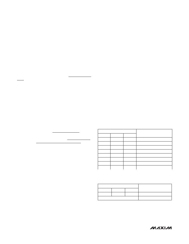
�Table 1� .� Jumper� Settings�
�7)�
�Go� to� the� Windows� System Properties� window�
�(Windows� logo� key� +� Pause� Break� key� from� key-�
�board)� to� locate� and� open� the� Device Manager� .�
�Under� the� Universal Serial Bus Controllers� subject�
�directory,� verify� that� the� USB� 2.0� signal� source� is�
�recognized� through� the� USB� port� .�
�SHUNT� POSITION�
�JU1� JU2� JU3�
�2-3� 2-3� 2-3�
�1-2� 2-3� 2-3�
�2-3� 1-2� 2-3�
�1-2� 1-2� 2-3�
�DESCRIPTION�
�Shutdown�
�Illegal� state�
�J1� and� J3� connected�
�J2� and� J3� connected�
�2-3�
�1-2�
�2-3�
�1-2*�
�2-3�
�2-3�
�1-2�
�1-2*�
�1-2�
�1-2�
�1-2�
�1-2*�
�J2� and� J4� connected�
�J1� and� J4� connected�
�Illegal� state�
�Shutdown�
�*Default� position.�
�Table 2.� Test� Circuit� Jumper� Settings�
�JU4�
�2-3�
�SHUNT� POSITION�
�JU5�
�1-2�
�JU6�
�2-3�
�DESCRIPTION�
�On�
�Windows,� Windows� XP,� and� Windows� Vista� are� registered�
�trademarks� of� Microsoft� Corp.�
�All� other� combinations�
�Off�
�2�
�______________________________________________________________________________________�
�相关PDF资料 |
PDF描述 |
|---|---|
| MAX5079EVKIT | EVAL KIT FOR MAX5079 |
| MAX5432EVKIT+ | KIT EVAL FOR MAX5432 |
| MAX5474EVKIT+ | KIT EVAL FOR MAX5474 |
| MAX5488EVKIT# | KIT EVALUATION FOR MAX5488 |
| MAX5498EVKIT+ | KIT EVAL FOR MAX5498 |
相关代理商/技术参数 |
参数描述 |
|---|---|
| MAX4989EVKIT+ | 功能描述:交换机 IC 开发工具 MAX4989 Eval Kit RoHS:否 制造商:Maxim Integrated 产品:Evaluation Kits 类型:USB Power Switches 工具用于评估:MAX4984E 工作电源电压:2.8 V to 5.5 V |
| MAX498CWI | 功能描述:多路器开关 IC RoHS:否 制造商:Texas Instruments 通道数量:1 开关数量:4 开启电阻(最大值):7 Ohms 开启时间(最大值): 关闭时间(最大值): 传播延迟时间:0.25 ns 工作电源电压:2.3 V to 3.6 V 工作电源电流: 最大工作温度:+ 85 C 安装风格:SMD/SMT 封装 / 箱体:UQFN-16 |
| MAX498CWI+ | 功能描述:多路器开关 IC RoHS:否 制造商:Texas Instruments 通道数量:1 开关数量:4 开启电阻(最大值):7 Ohms 开启时间(最大值): 关闭时间(最大值): 传播延迟时间:0.25 ns 工作电源电压:2.3 V to 3.6 V 工作电源电流: 最大工作温度:+ 85 C 安装风格:SMD/SMT 封装 / 箱体:UQFN-16 |
| MAX498CWI+T | 功能描述:多路器开关 IC RoHS:否 制造商:Texas Instruments 通道数量:1 开关数量:4 开启电阻(最大值):7 Ohms 开启时间(最大值): 关闭时间(最大值): 传播延迟时间:0.25 ns 工作电源电压:2.3 V to 3.6 V 工作电源电流: 最大工作温度:+ 85 C 安装风格:SMD/SMT 封装 / 箱体:UQFN-16 |
| MAX498CWI-T | 功能描述:多路器开关 IC RoHS:否 制造商:Texas Instruments 通道数量:1 开关数量:4 开启电阻(最大值):7 Ohms 开启时间(最大值): 关闭时间(最大值): 传播延迟时间:0.25 ns 工作电源电压:2.3 V to 3.6 V 工作电源电流: 最大工作温度:+ 85 C 安装风格:SMD/SMT 封装 / 箱体:UQFN-16 |
发布紧急采购,3分钟左右您将得到回复。