- 您现在的位置:买卖IC网 > PDF目录14396 > MAX5033CUPA+ (Maxim Integrated Products)IC REG BUCK 12V 0.5A 8DIP PDF资料下载
参数资料
| 型号: | MAX5033CUPA+ |
| 厂商: | Maxim Integrated Products |
| 文件页数: | 10/17页 |
| 文件大小: | 0K |
| 描述: | IC REG BUCK 12V 0.5A 8DIP |
| 产品培训模块: | Lead (SnPb) Finish for COTS Obsolescence Mitigation Program |
| 标准包装: | 50 |
| 类型: | 降压(降压) |
| 输出类型: | 固定 |
| 输出数: | 1 |
| 输出电压: | 12V |
| 输入电压: | 7.5 V ~ 76 V |
| PWM 型: | 电压模式 |
| 频率 - 开关: | 125kHz |
| 电流 - 输出: | 500mA |
| 同步整流器: | 无 |
| 工作温度: | 0°C ~ 85°C |
| 安装类型: | 通孔 |
| 封装/外壳: | 8-DIP(0.300",7.62mm) |
| 包装: | 管件 |
| 供应商设备封装: | 8-PDIP |
�� �
�
�MAX5033�
�500mA,� 76V,� High-Efficiency,� MAXPower�
�Step-Down� DC-DC� Converter�
�The� MAX5033� features� internal� compensation� for� opti-�
�mum� closed-loop� bandwidth� and� phase� margin.� With�
�the� preset� compensation,� it� is� strongly� advised� to� sense�
�the� output� immediately� after� the� primary� LC.�
�Inductor� Selection�
�The� choice� of� an� inductor� is� guided� by� the� voltage� dif-�
�ference� between� V� IN� and� V� OUT� ,� the� required� output�
�current,� and� the� operating� frequency� of� the� circuit.� Use�
�an� inductor� with� a� minimum� value� given� by:�
�load� current� to� avoid� forward� biasing� of� the� internal�
�body� diode� (LX� to� ground).� Internal� body-diode� con-�
�duction� may� cause� excessive� junction� temperature� rise�
�and� thermal� shutdown.� Use� Table� 1� to� choose� the�
�proper� rectifier� at� different� input� voltages� and� output�
�current.�
�Input� Bypass� Capacitor�
�The� discontinuous� input-current� waveform� of� the� buck�
�converter� causes� large� ripple� currents� in� the� input�
�L� =�
�(� V� IN� ?� V� OUT� )� � D�
�0� .� 3� � I� OUTMAX� � f� SW�
�capacitor.� The� switching� frequency,� peak� inductor� cur-�
�rent,� and� the� allowable� peak-to-peak� voltage� ripple� that�
�reflects� back� to� the� source� dictate� the� capacitance�
�requirement.� The� MAX5033� high� switching� frequency�
�where:� D� =� V� OUT� /V� IN� ,� I� OUTMAX� is� the� maximum� output�
�current� required,� and� f� SW� is� the� operating� frequency� of�
�125kHz.� Use� an� inductor� with� a� maximum� saturation�
�current� rating� equal� to� at� least� the� peak� switch� current�
�limit� (I� LIM� ).� Use� inductors� with� low� DC� resistance� for�
�higher� efficiency.�
�Selecting� a� Rectifier�
�The� MAX5033� requires� an� external� Schottky� rectifier� as�
�a� freewheeling� diode.� Connect� this� rectifier� close� to� the�
�allows� the� use� of� smaller-value� input� capacitors.�
�The� input� ripple� is� comprised� of� ?� V� Q� (caused� by� the�
�capacitor� discharge)� and� ?� V� ESR� (caused� by� the� ESR� of�
�the� capacitor).� Use� low-ESR� aluminum� electrolytic�
�capacitors� with� high� ripple-current� capability� at� the� input.�
�Assuming� that� the� contribution� from� the� ESR� and� capaci-�
�tor� discharge� is� equal� to� 90%� and� 10%,� respectively,� cal-�
�culate� the� input� capacitance� and� the� ESR� required� for� a�
�specified� ripple� using� the� following� equations:�
�?� ?� I� OUT� +� 2� ?� ?�
�device using short leads and short PC board traces.�
�Choose� a� rectifier� with� a� continuous� current� rating�
�greater� than� the� highest� expected� output� current.� Use� a�
�rectifier� with� a� voltage� rating� greater� than� the� maximum�
�ESR� IN� =�
�?� V� ESR�
�?� ?� I� L� ?�
�C� IN� =� OUT�
�expected input voltage, V� IN� . Use a low forward-voltage�
�Schottky� rectifier� for� proper� operation� and� high� efficien-�
�cy.� Avoid� higher� than� necessary� reverse-voltage�
�Schottky� rectifiers� that� have� higher� forward-voltage�
�where� :�
�I� � D(1� ?� D)�
�?� V� Q� � f� SW�
�drops.� Use� a� Schottky� rectifier� with� forward-voltage�
�drop� (V� FB� )� less� than� 0.45V� at� +25� °� C� and� maximum�
�?� I� L� =�
�(V� IN� ?� V� OUT� )� � V� OUT�
�V� IN� � f� SW� � L�
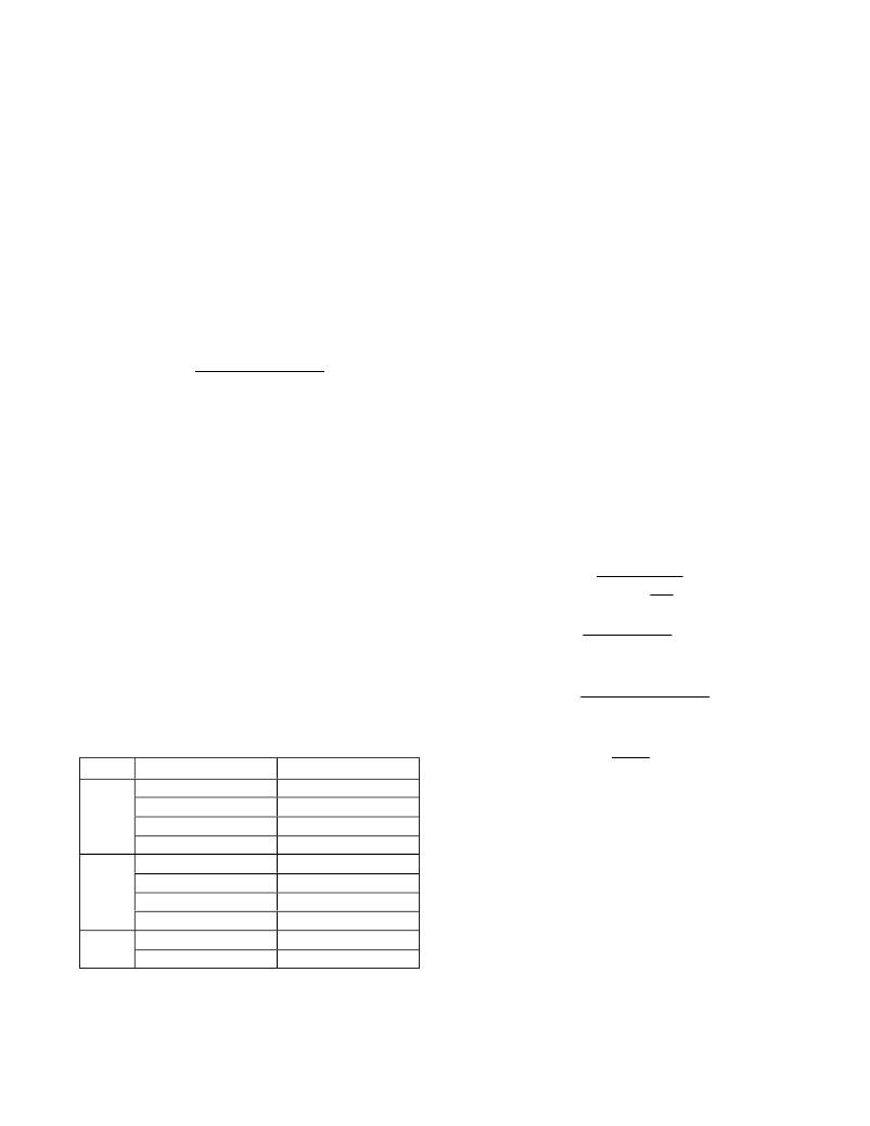
�Table� 1.� Diode� Selection�
�V� IN� (V)� DIODE� PART� NUMBER�
�MANUFACTURER�
�D� =�
�V� OUT�
�V� IN�
�15MQ040N�
�IR�
�I� OUT� is� the� maximum� output� current� of� the� converter� and�
�7.5� to� 36�
�7.5� to� 56�
�7.5� to� 76�
�B240A�
�B240�
�MBRS240,� MBRS1540�
�30BQ060�
�B360A�
�CMSH3-60�
�MBRD360,� MBR3060�
�50SQ100,� 50SQ80�
�MBRM5100�
�Diodes� Incorporated�
�Central� Semiconductor�
�ON� Semiconductor�
�IR�
�Diodes� Incorporated�
�Central� Semiconductor�
�ON� Semiconductor�
�IR�
�Diodes� Incorporated�
�f� SW� is� the� oscillator� switching� frequency� (125kHz).� For�
�example,� at� V� IN� =� 48V� and� V� OUT� =� 3.3V,� the� ESR� and�
�input� capacitance� are� calculated� for� the� input� peak-to-�
�peak� ripple� of� 100mV� or� less,� yielding� an� ESR� and�
�capacitance� value� of� 130m� ?� and� 27μF,� respectively.�
�Low-ESR,� ceramic,� multilayer� chip� capacitors� are� recom-�
�mended� for� size-optimized� application.� For� ceramic�
�capacitors,� assume� the� contribution� from� ESR� and� capac-�
�itor� discharge� is� equal� to� 10%� and� 90%,� respectively.�
�The� input� capacitor� must� handle� the� RMS� ripple� current�
�without� significant� rise� in� temperature.� The� maximum�
�capacitor� RMS� current� occurs� at� about� 50%� duty� cycle.�
�10�
�Maxim� Integrated�
�相关PDF资料 |
PDF描述 |
|---|---|
| MAX5033CUSA+ | IC REG BUCK 12V 0.5A 8SOIC |
| LQW15AN5N1C00D | INDUCTOR |
| HMC12DRTI-S93 | CONN EDGECARD 24POS DIP .100 SLD |
| LQW15AN56NH00D | INDUCTOR |
| LQW15AN51NH00D | INDUCTOR |
相关代理商/技术参数 |
参数描述 |
|---|---|
| MAX5033CUPA+ | 功能描述:直流/直流开关转换器 500mA 76V MAXPower Step-Down RoHS:否 制造商:STMicroelectronics 最大输入电压:4.5 V 开关频率:1.5 MHz 输出电压:4.6 V 输出电流:250 mA 输出端数量:2 最大工作温度:+ 85 C 安装风格:SMD/SMT |
| MAX5033CUSA | 功能描述:直流/直流开关转换器 RoHS:否 制造商:STMicroelectronics 最大输入电压:4.5 V 开关频率:1.5 MHz 输出电压:4.6 V 输出电流:250 mA 输出端数量:2 最大工作温度:+ 85 C 安装风格:SMD/SMT |
| MAX5033CUSA+ | 功能描述:直流/直流开关转换器 500mA 76V MAXPower Step-Down RoHS:否 制造商:STMicroelectronics 最大输入电压:4.5 V 开关频率:1.5 MHz 输出电压:4.6 V 输出电流:250 mA 输出端数量:2 最大工作温度:+ 85 C 安装风格:SMD/SMT |
| MAX5033CUSA+T | 功能描述:直流/直流开关转换器 500mA 76V MAXPower Step-Down RoHS:否 制造商:STMicroelectronics 最大输入电压:4.5 V 开关频率:1.5 MHz 输出电压:4.6 V 输出电流:250 mA 输出端数量:2 最大工作温度:+ 85 C 安装风格:SMD/SMT |
| MAX5033CUSA-T | 功能描述:直流/直流开关转换器 RoHS:否 制造商:STMicroelectronics 最大输入电压:4.5 V 开关频率:1.5 MHz 输出电压:4.6 V 输出电流:250 mA 输出端数量:2 最大工作温度:+ 85 C 安装风格:SMD/SMT |
发布紧急采购,3分钟左右您将得到回复。