- 您现在的位置:买卖IC网 > PDF目录2011 > MAX5774UCB+D (Maxim Integrated Products)IC DAC 14BIT 32CHAN SER 64-TQFP PDF资料下载
参数资料
| 型号: | MAX5774UCB+D |
| 厂商: | Maxim Integrated Products |
| 文件页数: | 10/28页 |
| 文件大小: | 0K |
| 描述: | IC DAC 14BIT 32CHAN SER 64-TQFP |
| 产品培训模块: | Lead (SnPb) Finish for COTS Obsolescence Mitigation Program |
| 标准包装: | 160 |
| 设置时间: | 20µs |
| 位数: | 14 |
| 数据接口: | 串行 |
| 转换器数目: | 32 |
| 电压电源: | 模拟和数字 |
| 工作温度: | 0°C ~ 85°C |
| 安装类型: | 表面贴装 |
| 封装/外壳: | 64-LQFP |
| 供应商设备封装: | 64-LQFP(10x10) |
| 包装: | 托盘 |
| 输出数目和类型: | 32 电压,单极 |
| 采样率(每秒): | * |
| 产品目录页面: | 1398 (CN2011-ZH PDF) |
第1页第2页第3页第4页第5页第6页第7页第8页第9页当前第10页第11页第12页第13页第14页第15页第16页第17页第18页第19页第20页第21页第22页第23页第24页第25页第26页第27页第28页
MAX5773/MAX5774/MAX5775
GAIN = 10/3 for the MAX5773/MAX5774/MAX5775.
Load-DAC (
LDAC) Input
The MAX5773/MAX5774/MAX5775 feature an active-
low LDAC input that allows the outputs (OUT_) to
update asynchronously. Keep LDAC high during nor-
mal operation (when the device is controlled only
through the serial interface). Drive LDAC low to simulta-
neously update all DAC outputs with data from their
respective input registers. Figure 2 shows the LDAC
timing with respect to OUT_.
A software command can also perform the LDAC oper-
ation. To initiate LDAC by software, set control bits
C3–C0 = 0010, address bits A5–A0 = 111111, and all
data bits to don’t care. See Table 3 for the data format.
This operation updates all DAC outputs simultaneously.
The software load-DAC command for all channels does
not affect the offset DAC.
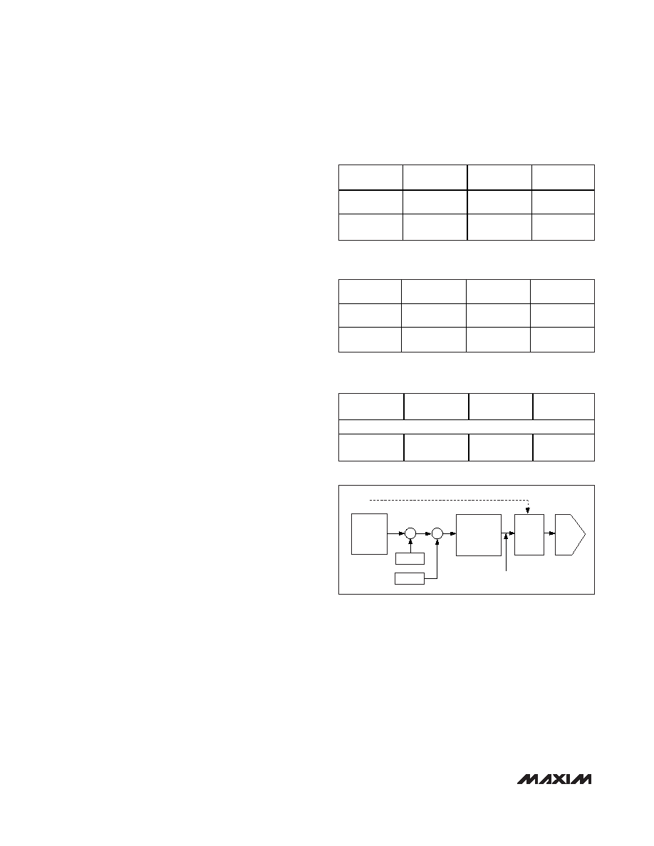
Software MAC-Bypass
The MAX5773/MAX5774/MAX5775 feature a software
MAC-bypass command that loads data into the DAC
directly from DIN. Software MAC-bypass loads one DAC,
a pair of DACs, or all 32 DACs with a data word (D13–D0
and S1, S0) entered at DIN and the selected DAC out-
put(s) are simultaneously updated. Software MAC-
bypass bypasses gain and offset calibration, sending
the input data directly to the DAC register immediately
updating the selected DAC outputs. After executing
MAC-bypass on a channel(s), previously calibrated data
can be reloaded into the DAC by executing software
load-DAC or hardware LDAC (see Figure 4). Using soft-
ware MAC-bypass, the DAC output(s) can be set to the
ground-sense value or any arbitrary value within the DAC
output voltage range.
To activate software MAC-bypass, set control bits
C3–C0 = 0111. The address bits (A5–A0) select the
DAC(s) to be updated and the data bits (D13–D0) con-
trol the DAC output voltage value. Table 4 shows the
input data format for the software-controlled MAC-
bypass command.
Reset (
RESET)
The MAX5773/MAX5774/MAX5775 feature an active-
low RESET logic input that asynchronously sets all the
registers to code 0000h (power-up state). The serial
interface can also issue a software-reset command.
Setting the control bits C3–C0 = 1111 performs the
same function as driving the logic input RESET low.
Table 5 shows the reset data format for the software-
controlled reset command. The software reset does not
work in daisy-chain mode. Reprogram the offset DAC
after asserting a software or hardware reset.
Serial Interface
The MAX5773/MAX5774/MAX5775 allow channel updates
either individually or in pairs. This is achieved by dividing
the 32 channels into two channel banks, with 16 channels
in each bank. Channel bank 0 contains output channels
OUT0–OUT15 and channel bank 1 contains channels
OUT16–OUT31. A channel from bank 0 is paired with a
channel from bank 1 and is ordered as OUT0:OUT16,
OUT1:OUT17...OUT14:OUT30, OUT15:OUT31.
A 3-wire SPI-/QSPI-/MICROWIRE- and DSP-compatible
serial interface controls the MAX5773/MAX5774/
MAX5775. The interface requires a
32-Channel, 14-Bit, Voltage-Output
DACs with Serial Interface
18
______________________________________________________________________________________
CONTROL
BITS
ADDRESS
BITS
DATA BITS
DON’T-CARE
BITS
C3–C0
A5–A0
D13–D0 and
S1, S0*
6 Don’t-Care
Bits
1111
XXXXXX
XXXXXXXXXX
XXXX00
XXXXXX
Table 5. Reset Data Format
*
S1 = S0 = 0 for proper 14-bit operation.
CONTROL
BITS
ADDRESS
BITS
DATA BITS
DON’T-CARE
BITS
C3–C0
A5–A0
D13–D0 and
S1, S0*
6 Don’t-Care
Bits
0111
See Figure 3
D13–D0,
S1, S0*
XXXXXX
Table 4. MAC-Bypass Data Format
*
S1 = S0 = 0 for proper 14-bit operation.
CONTROL
BITS
ADDRESS
BITS
DATA BITS
6 DON’T-
CARE BITS
MSB
LSB
C3–C0
A5–A0
D13–D0 and
S1, S0*
XXXXXX
Table 6. Serial Data Format
*
S1 = S0 = 0 for proper 14-bit operation.
INPUT_
REGISTER
GAIN
OFFSET
DAC_
REGISTER
CALIBRATED
DATA REGISTER
DAC_
LDAC
+
*
MAC-BYPASS
DIN
Figure 4. MAC-Bypass Functional Diagram
相关PDF资料 |
PDF描述 |
|---|---|
| MAX5811PEUT+T | IC DAC SERIAL 10BIT 1CH SOT23-6 |
| MAX5812PEUT+T | IC DAC SERIAL 12BIT 1CH SOT23-6 |
| MAX5815AAUD+T | IC DAC 12BIT SRL 4CH 14TSSOP |
| MAX5816ATB+T | IC DAC 12BIT SRL 4CH 10TDFN |
| MAX5820MEUA+ | IC DAC 8BIT DUAL 2WIRE SER 8UMAX |
相关代理商/技术参数 |
参数描述 |
|---|---|
| MAX5774UCB-TD | 功能描述:数模转换器- DAC RoHS:否 制造商:Texas Instruments 转换器数量:1 DAC 输出端数量:1 转换速率:2 MSPs 分辨率:16 bit 接口类型:QSPI, SPI, Serial (3-Wire, Microwire) 稳定时间:1 us 最大工作温度:+ 85 C 安装风格:SMD/SMT 封装 / 箱体:SOIC-14 封装:Tube |
| MAX5774UTK | 功能描述:数模转换器- DAC RoHS:否 制造商:Texas Instruments 转换器数量:1 DAC 输出端数量:1 转换速率:2 MSPs 分辨率:16 bit 接口类型:QSPI, SPI, Serial (3-Wire, Microwire) 稳定时间:1 us 最大工作温度:+ 85 C 安装风格:SMD/SMT 封装 / 箱体:SOIC-14 封装:Tube |
| MAX5774UTK+ | 功能描述:数模转换器- DAC 14-Bit 32Ch Precision DAC RoHS:否 制造商:Texas Instruments 转换器数量:1 DAC 输出端数量:1 转换速率:2 MSPs 分辨率:16 bit 接口类型:QSPI, SPI, Serial (3-Wire, Microwire) 稳定时间:1 us 最大工作温度:+ 85 C 安装风格:SMD/SMT 封装 / 箱体:SOIC-14 封装:Tube |
| MAX5774UTK+G074 | 功能描述:数模转换器- DAC 32-Channel 14-Bit Voltage-Output DAC with Serial Interface RoHS:否 制造商:Texas Instruments 转换器数量:1 DAC 输出端数量:1 转换速率:2 MSPs 分辨率:16 bit 接口类型:QSPI, SPI, Serial (3-Wire, Microwire) 稳定时间:1 us 最大工作温度:+ 85 C 安装风格:SMD/SMT 封装 / 箱体:SOIC-14 封装:Tube |
| MAX5774UTK+T | 功能描述:数模转换器- DAC 14-Bit 32Ch Precision DAC RoHS:否 制造商:Texas Instruments 转换器数量:1 DAC 输出端数量:1 转换速率:2 MSPs 分辨率:16 bit 接口类型:QSPI, SPI, Serial (3-Wire, Microwire) 稳定时间:1 us 最大工作温度:+ 85 C 安装风格:SMD/SMT 封装 / 箱体:SOIC-14 封装:Tube |
发布紧急采购,3分钟左右您将得到回复。