- 您现在的位置:买卖IC网 > PDF目录10760 > MAX5812MEUT#TG16 (Maxim Integrated Products)IC DAC 12BIT 2WIRE SER SOT23-6 PDF资料下载
参数资料
| 型号: | MAX5812MEUT#TG16 |
| 厂商: | Maxim Integrated Products |
| 文件页数: | 13/13页 |
| 文件大小: | 0K |
| 描述: | IC DAC 12BIT 2WIRE SER SOT23-6 |
| 产品培训模块: | Lead (SnPb) Finish for COTS |
| 产品变化通告: | Product Discontinuation 06/Feb/2012 |
| 标准包装: | 2,500 |
| 设置时间: | 4µs |
| 位数: | 12 |
| 数据接口: | I²C,串行 |
| 转换器数目: | 1 |
| 电压电源: | 单电源 |
| 功率耗散(最大): | 727mW |
| 工作温度: | -40°C ~ 85°C |
| 安装类型: | 表面贴装 |
| 封装/外壳: | SOT-23-6 |
| 供应商设备封装: | SOT-6 |
| 包装: | 带卷 (TR) |
| 输出数目和类型: | 1 电压,单极 |
| 采样率(每秒): | * |
MAX5812
12-Bit Low-Power, 2-Wire, Serial
Voltage-Output DAC
_______________________________________________________________________________________
9
low transition on SDA with SCL high. A STOP condition
is a low-to-high transition on SDA while SCL is high
(Figure 2). A START condition from the master signals
the beginning of a transmission to the MAX5812. The
master terminates transmission by issuing a not
acknowledge followed by a STOP condition (see the
Acknowledge Bit section). The STOP condition frees the
bus. If a repeated START condition (Sr) is generated
instead of a STOP condition, the bus remains active.
When a STOP condition or incorrect address is detect-
ed, the MAX5812 internally disconnects SCL from the
serial interface until the next START condition, minimiz-
ing digital noise and feedthrough.
Early STOP Conditions
The MAX5812 recognizes a STOP condition at any point
during transmission except when a STOP condition
occurs in the same high pulse as a START condition
(Figure 3). This condition is not a legal I2C format, at
least one clock pulse must separate any START and
STOP conditions.
Repeated START Conditions
A repeated start (Sr) condition might indicate a change
of data direction on the bus. Such a change occurs
when a command word is required to initiate a read
operation. Sr also can be used when the bus master is
writing to several I2C devices and does not want to
relinquish control of the bus. The MAX5812 serial inter-
face supports continuous write operations with or with-
out an Sr condition separating them. Continuous read
operations require Sr conditions because of the change
in direction of data flow.
Acknowledge Bit (ACK)
The acknowledge bit (ACK) is the ninth bit attached to
any 8-bit data word. ACK is always generated by the
receiving device. The MAX5812 generates an ACK
when receiving an address or data by pulling SDA low
during the ninth clock period. When transmitting data,
the MAX5812 waits for the receiving device to generate
an ACK. Monitoring ACK allows detection of unsuc-
cessful data transfers. An unsuccessful data transfer
occurs if a receiving device is busy or if a system fault
has occurred. In the event of an unsuccessful data
transfer, the bus master should reattempt communica-
tion at a later time.
Slave Address
A bus master initiates communication with a slave
device by issuing a START condition followed by the
7-bit slave address (Figure 4). When idle, the MAX5812
waits for a START condition followed by its slave
address. The serial interface compares each address
value bit-by-bit, allowing the interface to power-down
immediately when an incorrect address is detected.
The LSB of the address word is the Read/Write (R/W)
bit. R/W indicates whether the master is writing to or
reading from the MAX5812 (R/W = 0 selects the write
condition, R/W = 1 selects the read condition). After
receiving the proper address, the MAX5812 issues an
ACK by pulling SDA low for one clock cycle.
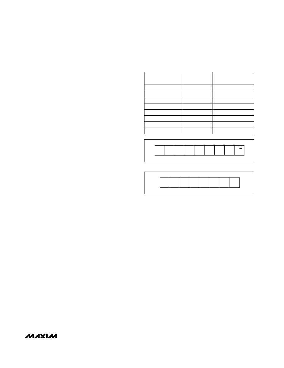
The MAX5812 has eight factory/user-programmed
addresses (Table 2). Address bits A6 through A1 are
preset; A0 is controlled by ADD. Connecting ADD to
GND sets A0 = 0. Connecting ADD to VDD sets A0 = 1.
This feature allows up to eight MAX5812s to share a bus.
Write Data Format
In write mode (R/W = 0), data that follows the address
byte controls the MAX5812 (Figure 5). Bits C3–C0 con-
figure the MAX5812 (Table 3). Bits D11–D0 are DAC
data. Input and DAC registers update on the falling
edge of SCL during the acknowledge bit. Should the
write cycle be prematurely aborted, data will not be
updated and the write cycle must be repeated. Figure
6 shows two example write data sequences.
S
A6A5A4A3A2A1A0
R/W
Figure 4. Slave Address Byte Definition
Table 2. MAX5812 I2C Slave Addresses
PART
VADD
DEVICE ADDRESS
(A6...A0)
MAX5812L
GND
0010 000
MAX5812L
VDD
0010 001
MAX5812M
GND
0010 010
MAX5812M
VDD
0010 011
MAX5812N
GND
0110 100
MAX5812N
VDD
0110 101
MAX5812P
GND
1010 100
MAX5812P
VDD
1010 101
C3
C2
C1
C0
D11
D10
D9
D8
Figure 5. Command Byte Definition
相关PDF资料 |
PDF描述 |
|---|---|
| MAX5556GSA+ | IC DAC STEREO AUDIO 8-SOIC |
| VI-2NM-CU-F1 | CONVERTER MOD DC/DC 10V 200W |
| VI-2NK-CU-F2 | CONVERTER MOD DC/DC 40V 200W |
| VI-2NJ-IW-S | CONVERTER MOD DC/DC 36V 100W |
| MX7248JP+ | IC DAC 12BIT MULT 20-PLCC |
相关代理商/技术参数 |
参数描述 |
|---|---|
| MAX5812NEUT | 制造商:Maxim Integrated Products 功能描述:12-BIT LOW-POWER 2-WIRE SERIAL V - Cut Tape Product |
| MAX5812NEUT+T | 功能描述:数模转换器- DAC 12-Bit Precision DAC RoHS:否 制造商:Texas Instruments 转换器数量:1 DAC 输出端数量:1 转换速率:2 MSPs 分辨率:16 bit 接口类型:QSPI, SPI, Serial (3-Wire, Microwire) 稳定时间:1 us 最大工作温度:+ 85 C 安装风格:SMD/SMT 封装 / 箱体:SOIC-14 封装:Tube |
| MAX5812NEUT-T | 功能描述:数模转换器- DAC RoHS:否 制造商:Texas Instruments 转换器数量:1 DAC 输出端数量:1 转换速率:2 MSPs 分辨率:16 bit 接口类型:QSPI, SPI, Serial (3-Wire, Microwire) 稳定时间:1 us 最大工作温度:+ 85 C 安装风格:SMD/SMT 封装 / 箱体:SOIC-14 封装:Tube |
| MAX5812PEUT | 制造商:Maxim Integrated Products 功能描述:12-BIT LOW-POWER 2-WIRE SERIAL V - Rail/Tube |
| MAX5812PEUT+T | 功能描述:数模转换器- DAC 12-Bit Precision DAC RoHS:否 制造商:Texas Instruments 转换器数量:1 DAC 输出端数量:1 转换速率:2 MSPs 分辨率:16 bit 接口类型:QSPI, SPI, Serial (3-Wire, Microwire) 稳定时间:1 us 最大工作温度:+ 85 C 安装风格:SMD/SMT 封装 / 箱体:SOIC-14 封装:Tube |
发布紧急采购,3分钟左右您将得到回复。