- 您现在的位置:买卖IC网 > PDF目录20051 > MAX5904ESA+ (Maxim Integrated)IC HOT-SWAP CTRLR DUAL 8-SOIC PDF资料下载
参数资料
| 型号: | MAX5904ESA+ |
| 厂商: | Maxim Integrated |
| 文件页数: | 9/24页 |
| 文件大小: | 633K |
| 描述: | IC HOT-SWAP CTRLR DUAL 8-SOIC |
| 产品培训模块: | Lead (SnPb) Finish for COTS Obsolescence Mitigation Program |
| 标准包装: | 100 |
| 类型: | 热交换控制器 |
| 应用: | 通用型,PCI Express? |
| 内部开关: | 无 |
| 电源电压: | 1 V ~ 13.2 V |
| 工作温度: | -40°C ~ 85°C |
| 安装类型: | 表面贴装 |
| 封装/外壳: | 8-SOIC(0.154",3.90mm 宽) |
| 供应商设备封装: | 8-SOIC |
| 包装: | 管件 |
Detailed Description
The MAX5904MAX5909 are circuit breaker ICs for hot-
swap applications where a line card is inserted into a
live backplane. These devices hot swap supplies rang-
ing from +1V to +13.3V, provided one supply is at or
above 2.7V. Normally, when a line card is plugged into
a live backplane, the cards discharged filter capacitors
provide low impedance that can momentarily cause the
main power supply to collapse. The MAX5904
MAX5909 reside either on the backplane or on the
removable card to provide inrush current limiting and
short-circuit protection. This is achieved by using exter-
nal n-channel MOSFETs, external current-sense resis-
tors, and two on-chip comparators. Figure 1 shows the
MAX5906MAX5909 functional diagram.
The MAX5904/MAX5905 have a fixed startup period
and current-limit threshold. The startup period and cur-
rent-limit threshold of the MAX5906MAX5909 can be
adjusted with external resistors.
Startup Period
R
TIM
sets the duration of the startup period for the
MAX5906MAX5909 from 0.4ms to 50ms (see the
Setting the Startup Period, R
TIM
section). The duration
of the startup period is fixed at 9ms for the MAX5904/
MAX5905. The startup period begins after the following
three conditions are met:
1) V
IN1
or V
IN2
exceeds the UVLO threshold (2.4V) for
the UVLO to startup delay (37.5ms).
2) V
ON
exceeds the channel 1 ON threshold (0.825V).
V
ON
should be delayed from the application of a
steep rising edge at IN_ by inserting a minimum RC
time delay of 20祍.
3) The device is not latched or in its autoretry delay. (See
Latched and Autoretry Fault Management section.)
The MAX5904MAX5909 limit the load current if an
overcurrent fault occurs during startup. The slow com-
parator is disabled during the startup period and the
load current can be limited in two ways:
1) Slowly enhancing the MOSFETs by limiting the
MOSFET gate charging current
2) Limiting the voltage across the external current-
sense resistor.
During the startup period, the gate drive current is typi-
cally 100礎 and decreases with the increase of the
gate voltage (see the Typical Operating Character-
istics). This allows the controller to slowly enhance the
MOSFETs. If the fast comparator detects an overcur-
rent, the MAX5904MAX5909 regulate the gate voltage
to ensure that the voltage across the sense resistor
does not exceed V
SU,TH
. This effectively regulates the
inrush current during startup. Figure 2 shows the start-
up waveforms. PGOOD goes high impedance 0.75ms
after the startup period if no fault condition is present.
VariableSpeed/BiLevel Fault Protection
VariableSpeed/BiLevel fault protection incorporates two
comparators with different thresholds and response
times to monitor the load current (Figure 9). During the
startup period, protection is provided by limiting the
load current. Protection is provided in normal operation
(after the startup period has expired) by discharging
both MOSFET gates with a strong 3mA pulldown cur-
rent in response to a fault condition. After a fault,
PGOOD is pulled low, the MAX5905/MAX5907/
MAX5909 stay latched off and the MAX5904/MAX5906/
MAX5908 automatically restart.
Low-Voltage, Dual Hot-Swap Controllers/Power
Sequencers
_______________________________________________________________________________________________________ 9
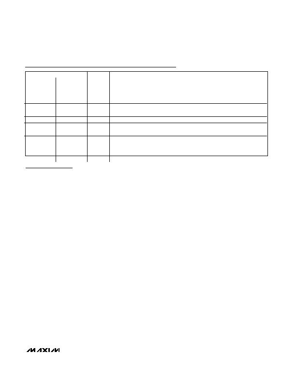
PIN
MAX5904/
MAX5905
MAX5906
MAX5909
NAME
FUNCTION
10
LIM2
Channel 2 Current-Limit Setting. Connect a resistor from LIM2 to GND to set
current-trip level. Connect to GND for the default 25mV threshold.
5
11
ON
On Comparator Input
6
12
GATE2
Channel 2 Gate-Drive Output. Connect to gate of external n-channel MOSFET.
7
13
SENSE2
Channel 2 Current-Sense Input. Connect R
SENSE2
from IN2 to SENSE2.
8
14
IN2
Channel 2 Supply Input. Connect to a supply voltage from 1V to 13.2V. Connect a
0.1礔 ceramic bypass capacitor from IN2 to GND to filter high-frequency noise.
15
INC+
Uncommitted Comparator Noninverting Input
16
OUTC
Uncommitted Comparator Open-Drain Output. Actively held low when V
INC+
is less
than 1.236V.
Pin Description (continued)
相关PDF资料 |
PDF描述 |
|---|---|
| VI-25K-CW-S | CONVERTER MOD DC/DC 40V 100W |
| GSC40DRAI | CONN EDGECARD 80POS R/A .100 SLD |
| RSA32DTMN | CONN EDGECARD 64POS R/A .125 SLD |
| GBC17DRYN-S13 | CONN EDGECARD 34POS .100 EXTEND |
| RMA32DTMN | CONN EDGECARD 64POS R/A .125 SLD |
相关代理商/技术参数 |
参数描述 |
|---|---|
| MAX5904ESA+ | 功能描述:热插拔功率分布 13.2V Hot-Swap Controller RoHS:否 制造商:Texas Instruments 产品:Controllers & Switches 电流限制: 电源电压-最大:7 V 电源电压-最小:- 0.3 V 工作温度范围: 功率耗散: 安装风格:SMD/SMT 封装 / 箱体:MSOP-8 封装:Tube |
| MAX5904ESA+T | 功能描述:热插拔功率分布 13.2V Hot-Swap Controller RoHS:否 制造商:Texas Instruments 产品:Controllers & Switches 电流限制: 电源电压-最大:7 V 电源电压-最小:- 0.3 V 工作温度范围: 功率耗散: 安装风格:SMD/SMT 封装 / 箱体:MSOP-8 封装:Tube |
| MAX5904ESA-T | 功能描述:热插拔功率分布 RoHS:否 制造商:Texas Instruments 产品:Controllers & Switches 电流限制: 电源电压-最大:7 V 电源电压-最小:- 0.3 V 工作温度范围: 功率耗散: 安装风格:SMD/SMT 封装 / 箱体:MSOP-8 封装:Tube |
| MAX5904USA | 功能描述:热插拔功率分布 RoHS:否 制造商:Texas Instruments 产品:Controllers & Switches 电流限制: 电源电压-最大:7 V 电源电压-最小:- 0.3 V 工作温度范围: 功率耗散: 安装风格:SMD/SMT 封装 / 箱体:MSOP-8 封装:Tube |
| MAX5904USA+ | 功能描述:热插拔功率分布 13.2V Hot-Swap Controller RoHS:否 制造商:Texas Instruments 产品:Controllers & Switches 电流限制: 电源电压-最大:7 V 电源电压-最小:- 0.3 V 工作温度范围: 功率耗散: 安装风格:SMD/SMT 封装 / 箱体:MSOP-8 封装:Tube |
发布紧急采购,3分钟左右您将得到回复。