- 您现在的位置:买卖IC网 > PDF目录19782 > MAX5936LAESA+T (Maxim Integrated)IC HOT-SWAP CTRLR -48V 8-SOIC PDF资料下载
参数资料
| 型号: | MAX5936LAESA+T |
| 厂商: | Maxim Integrated |
| 文件页数: | 11/23页 |
| 文件大小: | 382K |
| 描述: | IC HOT-SWAP CTRLR -48V 8-SOIC |
| 产品培训模块: | Lead (SnPb) Finish for COTS Obsolescence Mitigation Program |
| 标准包装: | 2,500 |
| 类型: | 热交换控制器 |
| 应用: | 通用 |
| 内部开关: | 无 |
| 电源电压: | -10 V ~ -80 V |
| 工作温度: | -40°C ~ 85°C |
| 安装类型: | 表面贴装 |
| 封装/外壳: | 8-SOIC(0.154",3.90mm 宽) |
| 供应商设备封装: | 8-SOIC |
| 包装: | 带卷 (TR) |
-48V Hot-Swap Controllers with V
IN
Step Immunity and No R
SENSE
______________________________________________________________________________________ 11
Latched Fault Management
(MAX5936L_/MAX5937L_)
When the MAX5936L_/MAX5937L_ enter fault manage-
ment, they remain in this condition indefinitely until the
power is recycled or until UVLO is brought below
1.125V for 1.5ms (typ) (when the short-circuit or circuit-
breaker fault has cleared, the sequencer initiates a load-
probe test). If this is successful, it starts a normal
power-up GATE cycle. A manual reset circuit (Figure 8)
can be used to clear the latch.
Circuit-Breaker Thresholds
The MAX5936/MAX5937 are available with 100mV,
200mV, and 400mV circuit-breaker thresholds. The
short-circuit voltage threshold (V
SC
) is twice the circuit-
breaker threshold voltage (V
CB
). In the MAX5936/
MAX5937, V
CB
and V
SC
are temperature-compensated
(increasing with temperature) to track the normalized
temperature gradient of typical power MOSFETs.
The proper circuit-breaker threshold for an application
depends on the R
DS(ON)
of the external power MOSFET
and the maximum current the load is expected to draw.
To avoid false fault indication and dropping of the load,
the designer must take into account the load response
to voltage ripples and noise from the backplane power
supply, as well as switching currents in the downstream
DC-DC converter that is loading the circuit. While the
circuit-breaker threshold has glitch rejection that
ignores ripples and noise lasting less than 1.2ms, the
short-circuit detection is designed to respond very
quickly (less than 330ns) to a short circuit. V
SC
and
V
CB
must be selected from the three available ranges
with an adequate margin to cover all possible ripples,
noise, and system current transients.
The short-circuit and circuit-breaker voltages are sensed
at V
OUT
, which is the drain of the power MOSFET. The
R
DS(ON)
of the MOSFET is the current-sense resis-
tance, so the total current through the load and load
capacitance is the drain current of the power MOSFET.
Accordingly, the voltage at V
OUT
as a function of
MOSFET drain current is:
V
OUT
= I
D,MOSFET
x R
DS(ON)
The temperature compensation of the MAX5936/
MAX5937 is designed to track the R
DS(ON)
of the typi-
cal power MOSFET. Figure 9 shows the typical normal-
ized tempco of the circuit-breaker threshold along with
the normalized tempco of R
DS(ON)
for two typical power
MOSFETS. When determining the circuit-breaker
threshold in an application, go to the data sheet of the
power MOSFET and locate the manufacturers maxi-
mum R
DS(ON)
at +25癈 with a V
GS
of 10V. Next, find
the figure presenting the tempco of normalized R
DS(ON)
or on-resistance vs. temperature. Because this curve is
in normalized units typically with a value of 1 at +25癈,
it is possible to multiply the curve by the drain voltage
at +25癈 and convert the curve to drain voltage. Now
compare this curve to that of the MAX5936/MAX5937
normalized tempco of the circuit-breaker threshold
to make a determination of the tracking error in mV
between the power MOSFET [I
D,MOSFET
x R
DS(ON)
]
and the MAX5936/MAX5937 over the applications
operating temperature range. If the tempco of the
power MOSFET is greater than that of the MAX5936/
MAX5937, then additional margin will be required in
selecting the circuit-breaker and short-circuit voltages
at higher temperatures as compared to +25癈. When
dissipation in the power MOSFET is expected to lead to
local temperature elevation relative to ambient condi-
tions, then it becomes imperative that the MAX5936/
MAX5937 be located as close as possible to the power
MOSFET. The marginal effect of temperature differ-
ences on circuit-breaker and short-circuit voltages can
be estimated from a comparative plot such as Figure 9.
MAX5936LN and MAX5937LN
The MAX5936LN and MAX5937LN do not have circuit-
breaker and short-circuit thresholds and these faults
are ignored. For these devices PGOOD (PGOOD)
asserts 1.26ms after GATE has ramped to 90% of full
enhancement. The step detection function of the
MAX5936LN and MAX5937LN responds to V
IN
and
V
OUT
steps with the same voltage thresholds as the
MAX5936_C and MAX5937_C.
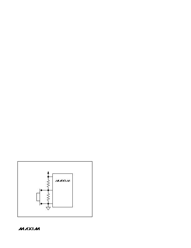
Figure 8. Resetting MAX5936L/MAX5937L after a Fault
Condition Using a Push-Button Switch
MAX5936L
MAX5937L
GND
UVLO
V
EE
V
IN
= (GND - V
EE
)
R2
R1
相关PDF资料 |
PDF描述 |
|---|---|
| VE-25Z-CX-F4 | CONVERTER MOD DC/DC 2V 30W |
| VE-25Z-CX-F3 | CONVERTER MOD DC/DC 2V 30W |
| LCMXO2280C-3M132C | IC PLD 2280LUTS 101I/O 132-BGA |
| RS2B-13-F | DIODE FAST REC 100V 1.5A SMB |
| MAX5936ANESA+T | IC HOT-SWAP CTRLR -48V 8-SOIC |
相关代理商/技术参数 |
参数描述 |
|---|---|
| MAX5936LBESA | 功能描述:热插拔功率分布 RoHS:否 制造商:Texas Instruments 产品:Controllers & Switches 电流限制: 电源电压-最大:7 V 电源电压-最小:- 0.3 V 工作温度范围: 功率耗散: 安装风格:SMD/SMT 封装 / 箱体:MSOP-8 封装:Tube |
| MAX5936LBESA+ | 功能描述:热插拔功率分布 48V- Hot-Swap Controller RoHS:否 制造商:Texas Instruments 产品:Controllers & Switches 电流限制: 电源电压-最大:7 V 电源电压-最小:- 0.3 V 工作温度范围: 功率耗散: 安装风格:SMD/SMT 封装 / 箱体:MSOP-8 封装:Tube |
| MAX5936LBESA+T | 功能描述:热插拔功率分布 48V- Hot-Swap Controller RoHS:否 制造商:Texas Instruments 产品:Controllers & Switches 电流限制: 电源电压-最大:7 V 电源电压-最小:- 0.3 V 工作温度范围: 功率耗散: 安装风格:SMD/SMT 封装 / 箱体:MSOP-8 封装:Tube |
| MAX5936LBESA-T | 功能描述:热插拔功率分布 RoHS:否 制造商:Texas Instruments 产品:Controllers & Switches 电流限制: 电源电压-最大:7 V 电源电压-最小:- 0.3 V 工作温度范围: 功率耗散: 安装风格:SMD/SMT 封装 / 箱体:MSOP-8 封装:Tube |
| MAX5936LCESA | 功能描述:热插拔功率分布 RoHS:否 制造商:Texas Instruments 产品:Controllers & Switches 电流限制: 电源电压-最大:7 V 电源电压-最小:- 0.3 V 工作温度范围: 功率耗散: 安装风格:SMD/SMT 封装 / 箱体:MSOP-8 封装:Tube |
发布紧急采购,3分钟左右您将得到回复。