- 您现在的位置:买卖IC网 > PDF目录11565 > MAX5942ACSE+T (Maxim Integrated Products)IC IEEE 802.3AF POE SYSTM 16SOIC PDF资料下载
参数资料
| 型号: | MAX5942ACSE+T |
| 厂商: | Maxim Integrated Products |
| 文件页数: | 3/24页 |
| 文件大小: | 0K |
| 描述: | IC IEEE 802.3AF POE SYSTM 16SOIC |
| 产品培训模块: | Lead (SnPb) Finish for COTS Obsolescence Mitigation Program |
| 标准包装: | 2,500 |
| 控制器类型: | 以太网供电控制器(POE) |
| 接口: | IEEE 802.3af |
| 电源电压: | 48V |
| 电流 - 电源: | 1mA |
| 工作温度: | 0°C ~ 70°C |
| 安装类型: | 表面贴装 |
| 封装/外壳: | 16-SOIC(0.154",3.90mm 宽) |
| 供应商设备封装: | 16-SOIC |
| 包装: | 带卷 (TR) |
MAX5942A/MAX5942B
IEEE 802.3af Power-Over-Ethernet
Interface/PWM Controller for Power Devices
______________________________________________________________________________________
11
MAX5942A/MAX5942B
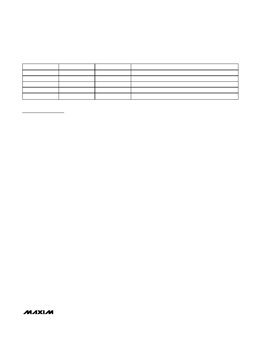
CLASS
USAGE
RCL ()
MAXIMUM POWER USED BY PD (W)
0
Default
10k
0.44 to 12.95
1
Optional
732
0.44 to 3.84
2
Optional
392
3.84 to 6.49
3
Optional
255
6.49 to 12.95
4
Not allowed
178
Reserved*
*Class 4 reserved for future use.
Table 1. PD Power Classification/RCL Selection
Detailed Description
The MAX5942A/MAX5942B integrate a complete power
IC for powered devices (PD) in a power-over-ethernet
(PoE) system. The MAX5942A/MAX5942B provide PD
Interface and a compact DC-DC PWM controller suitable
for flyback and forward converters in either isolated or
nonisolated designs.
The MAX5942A/MAX5942B PD interface complies with
the IEEE 802.3af standard, providing the PD with a
detection signature, a classification signature, and an
integrated isolation switch with programmable inrush
current control. These devices also feature power-mode
undervoltage lockout (UVLO) with wide hysteresis, and
power-good status outputs.
An integrated MOSFET provides PD isolation during
detection and classification. The MAX5942A/MAX5942B
guarantee a leakage current offset of less than 10A dur-
ing the detection phase. A programmable current limit
prevents high inrush current during power-on. The
devices feature power-mode UVLO with wide hysteresis
and long deglitch time to compensate for twisted-pair
cable resistive drop and to ensure glitch-free transition
between detection, classification, and power-on/off
phases. The MAX5942A/MAX5942B provide both active-
high (PGOOD) and active-low (PGOOD) outputs. Both
devices offer an adjustable UVLO threshold with a
default value compliant to the IEEE 802.3af standard.
The MAX5942A/MAX5942B are designed to work with or
without an external diode bridge in front of the PD.
Use the MAX5942A/MAX5942B PWM current-mode con-
trollers to design flyback- or forward-mode power sup-
plies. Current-mode operation simplifies control-loop
design while enhancing loop stability. An internal high-
voltage startup regulator allows the device to connect
directly to the input supply without an external startup
resistor. Current from the internal regulator starts the con-
troller. Once the tertiary winding voltage is established,
the internal regulator is switched off and bias current
for running the PWM controller is derived from the
tertiary winding. The internal oscillator is set to 275kHz
and trimmed to ±10%. This permits the use of small
magnetic components to minimize board space. Both the
MAX5942A and MAX5942B can be used in power sup-
plies providing multiple output voltages. A functional dia-
gram of the PWM controller is shown in Figure 4. Typical
application circuits for forward and flyback topologies are
shown in Figure 5 and Figure 6, respectively.
Powered Device Interface
Operating Modes
The PD front-end section of the MAX5942A/MAX5942B
operates in three different modes: PD detection signa-
ture, PD classification, and PD power, depending on its
input voltage (VIN = GND - VEE). All voltage thresholds
are designed to operate with or without the optional
diode bridge while still complying with the IEEE 802.3af
standard (see Application Circuit 1).
Detection Mode (1.4V ≤ VIN ≤ 10.1V)
In detection mode, the power source equipment (PSE)
applies two voltages on VIN in the range of 1.4V to
10.1V (1V step minimum), and then records the current
measurements at the two points. The PSE then com-
putes V/I to ensure the presence of the 25.5k sig-
nature
resistor.
In
this
mode,
most
of
the
MAX5942A/MAX5942B internal circuitry is off and the
offset current is less than 10A.
If the voltage applied to the PD is reversed, install pro-
tection diodes on the input terminal to prevent internal
damage to the MAX5942A/MAX5942B (see Figures 8
and 9). Since the PSE uses a slope technique (V/I) to
calculate the signature resistance, the DC offset due to
the protection diodes is subtracted and does not affect
the detection process.
Classification Mode (12.6V ≤ VIN ≤ 20V)
In the classification mode, the PSE classifies the PD
based on the power consumption required by the PD.
This allows the PSE to efficiently manage power distribu-
tion. The IEEE 802.3af standard defines five different
classes as shown in Table 1. An external resistor (RCL)
connected from RCL to VEE sets the classification current.
相关PDF资料 |
PDF描述 |
|---|---|
| V375A24C400BL3 | CONVERTER MOD DC/DC 24V 400W |
| MAX5941AESE+T | IC IEEE 802.3AF-COMP POE 16-SOIC |
| GRM219R72A331KA01D | CAP CER 330PF 100V 10% X7R 0805 |
| MAX5941BCSE+T | IC IEEE 802.3AF-COMP POE 16-SOIC |
| PIC24F08KA101T-I/SS | IC PIC MCU FLASH 8KB 20-SSOP |
相关代理商/技术参数 |
参数描述 |
|---|---|
| MAX5942AESE | 功能描述:电源开关 IC - POE / LAN RoHS:否 制造商:Fairchild Semiconductor 开关数量:Single 开关配置:SPST 开启电阻(最大值):7.3 Ohms 串话: 带宽: 开启时间(最大值):13 ns 关闭时间(最大值):20 ns 切换电压(最大): 工作电源电压:8 V to 26 V 最大工作温度:+ 125 C 安装风格:Through Hole 封装 / 箱体:TO-220F-6 |
| MAX5942AESE+ | 功能描述:输入/输出控制器接口集成电路 IEEE 802.3af POE Int/PWM Controller RoHS:否 制造商:Silicon Labs 产品: 输入/输出端数量: 工作电源电压: 最大工作温度:+ 85 C 最小工作温度:- 40 C 安装风格:SMD/SMT 封装 / 箱体:QFN-64 封装:Tray |
| MAX5942AESE+T | 功能描述:输入/输出控制器接口集成电路 IEEE 802.3af POE Int/PWM Controller RoHS:否 制造商:Silicon Labs 产品: 输入/输出端数量: 工作电源电压: 最大工作温度:+ 85 C 最小工作温度:- 40 C 安装风格:SMD/SMT 封装 / 箱体:QFN-64 封装:Tray |
| MAX5942AESE-T | 功能描述:电源开关 IC - POE / LAN RoHS:否 制造商:Fairchild Semiconductor 开关数量:Single 开关配置:SPST 开启电阻(最大值):7.3 Ohms 串话: 带宽: 开启时间(最大值):13 ns 关闭时间(最大值):20 ns 切换电压(最大): 工作电源电压:8 V to 26 V 最大工作温度:+ 125 C 安装风格:Through Hole 封装 / 箱体:TO-220F-6 |
| MAX5942BCSE | 功能描述:电源开关 IC - POE / LAN RoHS:否 制造商:Fairchild Semiconductor 开关数量:Single 开关配置:SPST 开启电阻(最大值):7.3 Ohms 串话: 带宽: 开启时间(最大值):13 ns 关闭时间(最大值):20 ns 切换电压(最大): 工作电源电压:8 V to 26 V 最大工作温度:+ 125 C 安装风格:Through Hole 封装 / 箱体:TO-220F-6 |
发布紧急采购,3分钟左右您将得到回复。