- 您现在的位置:买卖IC网 > PDF目录11565 > MAX5942BESE+T (Maxim Integrated Products)IC IEEE 802.3AF POE SYSTM 16SOIC PDF资料下载
参数资料
| 型号: | MAX5942BESE+T |
| 厂商: | Maxim Integrated Products |
| 文件页数: | 2/24页 |
| 文件大小: | 0K |
| 描述: | IC IEEE 802.3AF POE SYSTM 16SOIC |
| 产品培训模块: | Lead (SnPb) Finish for COTS Obsolescence Mitigation Program |
| 标准包装: | 2,500 |
| 控制器类型: | 以太网供电控制器(POE) |
| 接口: | IEEE 802.3af |
| 电源电压: | 48V |
| 电流 - 电源: | 1mA |
| 工作温度: | -40°C ~ 85°C |
| 安装类型: | 表面贴装 |
| 封装/外壳: | 16-SOIC(0.154",3.90mm 宽) |
| 供应商设备封装: | 16-SOIC |
| 包装: | 带卷 (TR) |
MAX5942A/MAX5942B
IEEE 802.3af Power-Over-Ethernet
Interface/PWM Controller for Power Devices
10
______________________________________________________________________________________
MAX5942A/MAX5942B
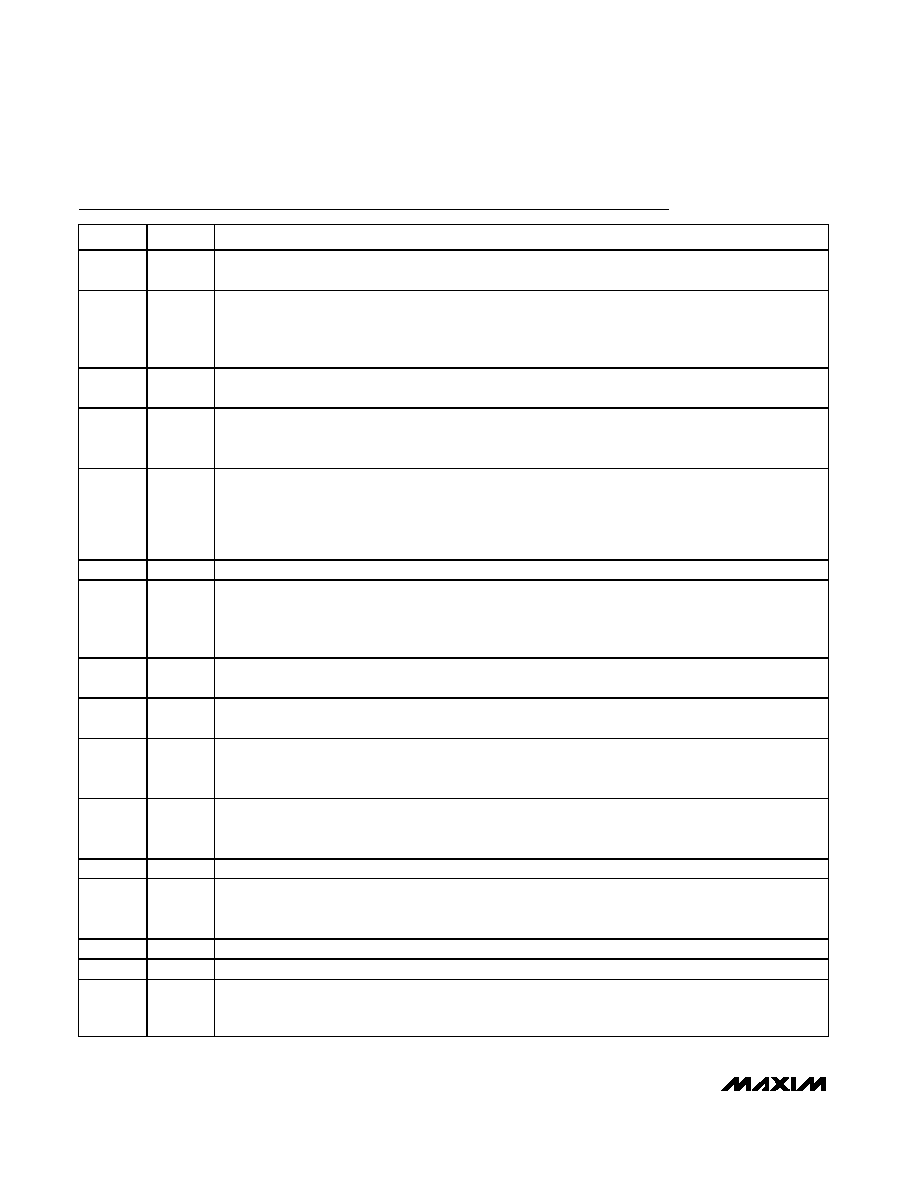
Pin Description
PIN
NAME
FUNCTION
1V+
High-Voltage Startup Input. Referenced to V-. Connect directly to an input voltage range between 18V to 67V.
Connects internally to a high-voltage linear regulator that generates VCC during startup.
2VDD
Line Regulator Input. Referenced to V-. VDD is the input to the linear regulator that generates VCC. For
supply voltages less than 36V, connect VDD and V+ to the supply. For supply voltages greater than 36V,
VDD receives its power from the tertiary winding of the transformer and accepts voltages from 13V to 36V.
Bypass VDD to V- with a 4.7F capacitor.
3FB
Fixed-Gain Inverting Amplifier Input. Referenced to V-. Connect a voltage-divider from the regulated output
to FB. The noninverting input of the amplifier is referenced to +2.4V
4
SS_SHDN
Soft-Start Timing Capacitor Connection. Referenced to V-. Ramp time to full current limit is approximately
0.45ms/nF. Bypass with a minimum 10nF capacitor to V-. A 2.4V reference voltage appears across the
capacitor. Disable the PWM controller by pulling SS_SHDN below 0.25V.
5
UVLO
Undervoltage Lockout Programming Input for Power Mode. Referenced to VEE. When UVLO is above its
threshold, the device enters the power mode. Connect UVLO to VEE to use the default undervoltage lockout
threshold. Connect UVLO to an external resistor-divider to define a threshold externally. The series
resistance value of the external resistors must add to 25.5k (±1%) and replaces the detection resistor. To
keep the device in undervoltage lockout, pull UVLO between VTH,G,UVLO and VREF,UVLO.
6
RCL
Classification Setting. Referenced to VEE. Add a resistor from RCL to VEE to set a PD class (see Table 1).
7
GATE
Gate of Internal N-Channel Power MOSFET. Referenced to VEE . GATE sources 10A when the device
enters the power mode. Connect an external 100V ceramic capacitor from GATE to VOUT to program the
inrush current. Pull GATE to VEE to turn off the internal MOSFET. The detection and classification functions
operate normally when GATE is pulled to VEE.
8VEE
Negative Input Power. Source of the integrated isolation N-channel power MOSFET. Connect VEE to
-48V.
9
OUT
Output Voltage. Referenced to VEE. Drain of the integrated isolation N-channel power MOSFET. Connect
OUT to V-.
10
PGOOD
Power-Good Indicator Output, Active High, Open Drain. PGOOD is referenced to OUT. PGOOD goes high
impedance when VOUT is within 1.2V of VEE and when GATE is 5V above VEE. Otherwise, PGOOD is pulled
to OUT (given that VOUT is at least 5V below GND).
11
PGOOD
Power-Good Indicator Output, Active Low, Open Drain. PGOOD is referenced to VEE. PGOOD is pulled to
VEE when VOUT is within 1.2V of VEE and when GATE is 5V above VEE. Otherwise, PGOOD goes high
impedance.
12
GND
Ground. Referenced to VEE. GND is the positive input power.
13
CS
Current-Sense Input. Referenced to V-. Turns power switch off if VCS rises above 465mV for cycle-by-cycle
current limiting. CS is also the feedback for the current-mode controller. CS connects to the PWM controller
through a leading-edge blanking circuit.
14
V-
Ground. V- is the ground terminal of the PWM controller.
15
NDRV
Gate Drive. Referenced to V-. Drives a high-voltage external N-channel power MOSFET.
16
VCC
Regulated IC Supply. Referenced to V-. Provides power for MAX5942_. VCC is regulated from VDD during
normal operation and from V+ during startup. Bypass VCC with a 10F tantalum capacitor in parallel with a
0.1F ceramic capacitor to V-.
相关PDF资料 |
PDF描述 |
|---|---|
| MAX5942AESE+T | IC IEEE 802.3AF POE SYSTM 16SOIC |
| PIC18LF23K22-E/SS | IC MCU 8BIT 8KB FLASH 28SSOP |
| V375A24C400BF2 | CONVERTER MOD DC/DC 24V 400W |
| MAX5942BCSE+T | IC IEEE 802.3AF POE SYSTM 16SOIC |
| V375A24C400BF | CONVERTER MOD DC/DC 24V 400W |
相关代理商/技术参数 |
参数描述 |
|---|---|
| MAX5943AEEE | 功能描述:热插拔功率分布 RoHS:否 制造商:Texas Instruments 产品:Controllers & Switches 电流限制: 电源电压-最大:7 V 电源电压-最小:- 0.3 V 工作温度范围: 功率耗散: 安装风格:SMD/SMT 封装 / 箱体:MSOP-8 封装:Tube |
| MAX5943AEEE+ | 功能描述:热插拔功率分布 FireWire Current Limiter RoHS:否 制造商:Texas Instruments 产品:Controllers & Switches 电流限制: 电源电压-最大:7 V 电源电压-最小:- 0.3 V 工作温度范围: 功率耗散: 安装风格:SMD/SMT 封装 / 箱体:MSOP-8 封装:Tube |
| MAX5943AEEE+T | 功能描述:热插拔功率分布 FireWire Current Limiter RoHS:否 制造商:Texas Instruments 产品:Controllers & Switches 电流限制: 电源电压-最大:7 V 电源电压-最小:- 0.3 V 工作温度范围: 功率耗散: 安装风格:SMD/SMT 封装 / 箱体:MSOP-8 封装:Tube |
| MAX5943AEEE-T | 功能描述:热插拔功率分布 RoHS:否 制造商:Texas Instruments 产品:Controllers & Switches 电流限制: 电源电压-最大:7 V 电源电压-最小:- 0.3 V 工作温度范围: 功率耗散: 安装风格:SMD/SMT 封装 / 箱体:MSOP-8 封装:Tube |
| MAX5943AEVKIT | 功能描述:电源管理IC开发工具 Evaluation Kit for the MAX5943A/B/C/D/E RoHS:否 制造商:Maxim Integrated 产品:Evaluation Kits 类型:Battery Management 工具用于评估:MAX17710GB 输入电压: 输出电压:1.8 V |
发布紧急采购,3分钟左右您将得到回复。