- 您现在的位置:买卖IC网 > PDF目录20026 > MAX5953AUTM+ (Maxim Integrated)IC INTERFACE 802.3AF 48TQFN PDF资料下载
参数资料
| 型号: | MAX5953AUTM+ |
| 厂商: | Maxim Integrated |
| 文件页数: | 17/27页 |
| 文件大小: | 371K |
| 描述: | IC INTERFACE 802.3AF 48TQFN |
| 产品培训模块: | Lead (SnPb) Finish for COTS Obsolescence Mitigation Program |
| 标准包装: | 43 |
| 类型: | 以太网供电开关(PoE) |
| 应用: | 远程外设(工业控制,相机,数据访问) |
| 内部开关: | 是 |
| 电源电压: | 11 V ~ 76 V |
| 工作温度: | 0°C ~ 85°C |
| 安装类型: | 表面贴装 |
| 封装/外壳: | 48-WFQFN 裸露焊盘 |
| 供应商设备封装: | 48-TQFN-EP(7x7) |
| 包装: | 管件 |
| 产品目录页面: | 1423 (CN2011-ZH PDF) |
第1页第2页第3页第4页第5页第6页第7页第8页第9页第10页第11页第12页第13页第14页第15页第16页当前第17页第18页第19页第20页第21页第22页第23页第24页第25页第26页第27页
The two-switch power topology recovers energy stored
in both the magnetizing and the parasitic leakage induc-
tances of the transformer. The Typical Application
Circuit, Figure 3, shows the schematic diagram of a -48V
input flyback converter using the MAX5953A. Figure 4
shows the schematic diagram of a -48V input forward
converter and a 5V, 3A output isolated power supply.
Voltage-Mode Control and the PWM Ramp
For voltage-mode control, the feed-forward PWM ramp
is generated at RCFF. From RCFF, connect a capacitor
to GND and a resistor to HVIN. The ramp generated is
applied to the noninverting input of the PWM compara-
tor at RAMP and has a minimum voltage of approxi-
mately 2V. The slope of the ramp is determined by the
voltage at HVIN and affects the overall loop gain. The
ramp peak must remain below the 5.5V dynamic range
of RCFF. Assuming the maximum duty cycle approach-
es 50% at a minimum input voltage (PWM UVLO turn-
on threshold), use the following formula to calculate the
minimum value of either the ramp capacitor or resistor:
where f
S
is the switching frequency, V
R(P-P)
is the peak-
to-peak ramp voltage (2V, typ). Select R
RCFF
resistance
value between 200k& and 600k&.
Maximize the signal-to-noise ratio by setting the ramp
peak as high as possible. Calculate the low-frequency,
small-signal gain of the power stage (the gain from the
inverting input of the PWM comparator to the output)
using the following formula:
G
PS
= N
SP
x R
RCFF
x C
RCFF
x f
S
where N
SP
is the secondary to primary power trans-
former turns ratio.
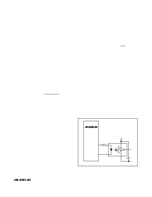
Secondary-Side Synchronization
The MAX5953A/MAX5953B/MAX5953C/MAX5953D
provide convenient synchronization for optional sec-
ondary-side synchronous rectifiers. Figure 5 shows the
connection diagram with a high-speed optocoupler.
Choose an optocoupler with a propagation delay of
less than 80ns. The synchronizing pulse is generated
approximately 110ns ahead of the main pulse that dri-
ves the two power MOSFETs.
Undervoltage Lockout for DC-DC Converter
Connect PGOOD to DCUVLO to ensure the PD interface
is ready prior to the DC-DC converter. The DCUVLO
block monitors the input voltage at HVIN through an
external resistive divider (R16 and R17) connected to
DCUVLO (see Figure 3). Use the following equation to
calculate R16 and R17:
where V
DCUVLOIN
is the desired input voltage lockout
level and V
DCUVLO
is the undervoltage lockout thresh-
old (1.25V, typ). Select the R17 resistance value
between 100k& and 500k&.
Optocoupled Feedback
Isolated voltage feedback is achieved by using an
optocoupler as shown in Figure 3. Connect the collec-
tor of the optotransistor to OPTO and a pullup resistor
between OPTO and REGOUT.
Internal Regulators
As soon as power is provided to HVIN, internal power
supplies power the DCUVLO detection circuitry.
REGOUT is used to drive the internal power MOSFETs.
Bypass REGOUT to GND with a minimum 2.2礔 ceram-
ic capacitor. The HVIN LDO steps down V
HVIN
to a
nominal output voltage (V
REGOUT
) of 8.75V. A second
parallel LDO powers REGOUT from INBIAS. A tertiary
winding connected through a diode to INBIAS powers
up REGOUT once switching commences. This powers
REGOUT to 10.5V (typ) and shuts off the current flow-
ing from HVIN to REGOUT. This results in a lower on-
chip power dissipation and higher efficiency.
V
V
R
R
DCUVLOIN
DCUVLO
=
?nbsp +
?/DIV>
?/DIV>
?/DIV>
?/DIV>
?/DIV>
?/DIV>
1
16
17
R
C
V
f V
RCFF
RCFF
IN EX
S R P P
?/DIV>
e
?nbsp ?/DIV>
,
2
IEEE 802.3af PD Interface and PWM Controllers
with Integrated Power MOSFETs
______________________________________________________________________________________ 17
C
+5V
R
MAX5953A
MAX5953B
MAX5953C
MAX5953D
PPWM
PGND
Figure 5. Secondary-Side Synchronous Rectifier Driver Using a
High-Speed Optocoupler
相关PDF资料 |
PDF描述 |
|---|---|
| MAX3736ETE+T | IC LSR DRVR 3.2GBPS 3.63V 16TQFN |
| 5747838-4 | CONN D-SUB RCPT R/A 25POS 30GOLD |
| VI-20R-CX | CONVERTER MOD DC/DC 7.5V 75W |
| 1-338311-2 | CONN D-SUB PLUG VERT 25POS |
| GRM188F51C104ZA01D | CAP CER 0.1UF 16V Y5V 0603 |
相关代理商/技术参数 |
参数描述 |
|---|---|
| MAX5953AUTM+ | 功能描述:电压模式 PWM 控制器 IEEE 802.3af PD Int & PWM Controller RoHS:否 制造商:Texas Instruments 输出端数量:1 拓扑结构:Buck 输出电压:34 V 输出电流: 开关频率: 工作电源电压:4.5 V to 5.5 V 电源电流:600 uA 最大工作温度:+ 125 C 最小工作温度:- 40 C 封装 / 箱体:WSON-8 封装:Reel |
| MAX5953AUTM+T | 功能描述:电压模式 PWM 控制器 IEEE 802.3af PD Int & PWM Controller RoHS:否 制造商:Texas Instruments 输出端数量:1 拓扑结构:Buck 输出电压:34 V 输出电流: 开关频率: 工作电源电压:4.5 V to 5.5 V 电源电流:600 uA 最大工作温度:+ 125 C 最小工作温度:- 40 C 封装 / 箱体:WSON-8 封装:Reel |
| MAX5953BUTM+ | 功能描述:电压模式 PWM 控制器 IEEE 802.3af PD Int & PWM Controller RoHS:否 制造商:Texas Instruments 输出端数量:1 拓扑结构:Buck 输出电压:34 V 输出电流: 开关频率: 工作电源电压:4.5 V to 5.5 V 电源电流:600 uA 最大工作温度:+ 125 C 最小工作温度:- 40 C 封装 / 箱体:WSON-8 封装:Reel |
| MAX5953BUTM+T | 功能描述:电压模式 PWM 控制器 IEEE 802.3af PD Int & PWM Controller RoHS:否 制造商:Texas Instruments 输出端数量:1 拓扑结构:Buck 输出电压:34 V 输出电流: 开关频率: 工作电源电压:4.5 V to 5.5 V 电源电流:600 uA 最大工作温度:+ 125 C 最小工作温度:- 40 C 封装 / 箱体:WSON-8 封装:Reel |
| MAX5953CUTM+ | 功能描述:电压模式 PWM 控制器 IEEE 802.3af PD Int & PWM Controller RoHS:否 制造商:Texas Instruments 输出端数量:1 拓扑结构:Buck 输出电压:34 V 输出电流: 开关频率: 工作电源电压:4.5 V to 5.5 V 电源电流:600 uA 最大工作温度:+ 125 C 最小工作温度:- 40 C 封装 / 箱体:WSON-8 封装:Reel |
发布紧急采购,3分钟左右您将得到回复。