- 您现在的位置:买卖IC网 > PDF目录16240 > MAX5974AEVKIT# (Maxim Integrated Products)EVAL KIT MAX5974A PDF资料下载
参数资料
| 型号: | MAX5974AEVKIT# |
| 厂商: | Maxim Integrated Products |
| 文件页数: | 16/27页 |
| 文件大小: | 0K |
| 描述: | EVAL KIT MAX5974A |
| 标准包装: | 1 |
| 系列: | * |
第1页第2页第3页第4页第5页第6页第7页第8页第9页第10页第11页第12页第13页第14页第15页当前第16页第17页第18页第19页第20页第21页第22页第23页第24页第25页第26页第27页
�� �
�
�MAX5974A/MAX5974B/MAX5974C/MAX5974D�
�Active-Clamped,� Spread-Spectrum,�
�Current-Mode� PWM� Controllers�
�V� =� R� EN1� �
�V� S(UVLO)�
�V� EN(MAX)�
�EN2�
�V� S(MAX)� �
�R� EN�
�UVLO� on� Power� Source�
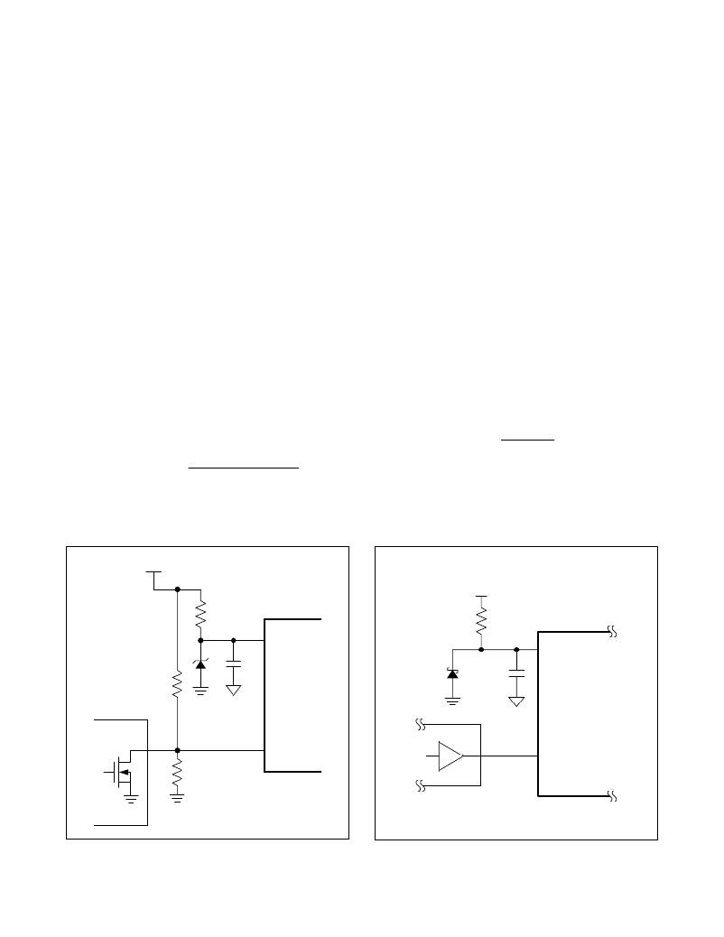
�The� enable� input� has� an� accurate� threshold� of� 1.26V�
�(max).� For� applications� that� require� a� UVLO� on� the�
�power� source,� connect� a� resistive� divider� from� the� power�
�source� to� EN� to� GND� as� shown� in� Figure� 1.� A� zener�
�diode� between� IN� and� GND� is� required� to� prevent� the�
�NDRV� and� AUXDRV� gate-drive� voltages� from� exceeding�
�20V,� the� maximum� allowed� gate� voltage� of� power� FETs.�
�The� external� zener� diode� should� clamp� in� the� following�
�range:�
�20V� >� V� Z� >� V� UVLO(MAX)�
�where� V� Z� is� the� zener� voltage� and� V� UVLO(MAX)� is� the�
�maximum� wakeup� level� (16.5V� or� 8.85V� depending� on�
�the� device� version).� An� 18V� zener� diode� is� the� best�
�choice.�
�Design� the� resistive� divider� by� first� selecting� the� value� of�
�R� EN1� to� be� on� the� order� of� 100kω.� Then� calculate� R� EN2�
�as� follows:�
�V� EN(MAX)�
�_�
�where� V� EN(MAX)� is� the� maximum� enable� threshold� volt-�
�age� and� is� equal� to� 1.26V� and� V� S(UVLO)� is� the� desired�
�UVLO� threshold� for� the� power� source,� below� which� the�
�device� is� disabled.�
�The� digital� output� connected� to� EN� should� be� capable�
�of� withstanding� more� than� the� maximum� supply� voltage.�
�MCU� Control� of� Enable� Input�
�When� using� a� microcontroller� GPIO� to� control� the� enable�
�input,� an� 18V� zener� diode� is� required� on� IN� as� shown� in�
�Figure� 2.�
�High-Voltage� Logic� Control� of� Enable� Input�
�In� the� case� where� EN� is� externally� controlled� by� a� high-�
�voltage� open-drain/collector� output� (e.g.,� PGOOD� indi-�
�cator� of� a� powered� device� controller),� connect� IN� to� EN�
�through� a� resistor� R� EN� and� connect� EN� to� an� open-drain�
�or� open-collector� output� as� shown� in� Figure� 3.� Select�
�R� EN� such� that� the� voltage� at� IN,� when� EN� is� low,� is� less�
�than� 20V� (i.e.,� the� maximum� gate� voltage� of� the� main� and�
�AUX� FETs):�
�<� 20V�
�R� EN� +� R� IN�
�where� V� S(MAX)� is� the� maximum� supply� voltage.� Obeying�
�this� relationship� eliminates� the� need� for� an� external� zener�
�diode.�
�The� digital� output� connected� to� EN� should� be� capable� of�
�withstanding� more� than� 20V.�
�V� S�
�V� S�
�R� IN�
�IN�
�R� IN�
�IN�
�R� EN1�
�18V�
�C� IN�
�MAX5974�
�18V�
�C� IN�
�MAX5974_�
�DIGITAL�
�MCU�
�CONTROL�
�N�
�R� EN2�
�EN�
�I/O�
�EN�
�Figure� 1.� Programmable� UVLO� for� the� Power� Source�
�16�
�Figure� 2.� MCU� Control� of� the� Enable� Input�
�Maxim� Integrated�
�相关PDF资料 |
PDF描述 |
|---|---|
| VE-J7J-EZ-F1 | CONVERTER MOD DC/DC 36V 25W |
| VE-J7H-EZ-F4 | CONVERTER MOD DC/DC 52V 25W |
| DS2762AE+ | IC MON BATT LI-ION HP 16-TSSOP |
| VE-J7H-EZ-F3 | CONVERTER MOD DC/DC 52V 25W |
| RP08-4805SA | CONV DC/DC 8W 36-75VIN 05VOUT |
相关代理商/技术参数 |
参数描述 |
|---|---|
| MAX5974AEVKIT# | 功能描述:电源管理IC开发工具 MAX5974A Eval Kit RoHS:否 制造商:Maxim Integrated 产品:Evaluation Kits 类型:Battery Management 工具用于评估:MAX17710GB 输入电压: 输出电压:1.8 V |
| MAX5974BETE+ | 功能描述:电流型 PWM 控制器 Current-Mode PWM Controller RoHS:否 制造商:Texas Instruments 开关频率:27 KHz 上升时间: 下降时间: 工作电源电压:6 V to 15 V 工作电源电流:1.5 mA 输出端数量:1 最大工作温度:+ 105 C 安装风格:SMD/SMT 封装 / 箱体:TSSOP-14 |
| MAX5974BETE+T | 功能描述:电流型 PWM 控制器 Current-Mode PWM Controller RoHS:否 制造商:Texas Instruments 开关频率:27 KHz 上升时间: 下降时间: 工作电源电压:6 V to 15 V 工作电源电流:1.5 mA 输出端数量:1 最大工作温度:+ 105 C 安装风格:SMD/SMT 封装 / 箱体:TSSOP-14 |
| MAX5974CETE+ | 功能描述:电流型 PWM 控制器 Current-Mode PWM Controller RoHS:否 制造商:Texas Instruments 开关频率:27 KHz 上升时间: 下降时间: 工作电源电压:6 V to 15 V 工作电源电流:1.5 mA 输出端数量:1 最大工作温度:+ 105 C 安装风格:SMD/SMT 封装 / 箱体:TSSOP-14 |
| MAX5974CETE+T | 功能描述:电流型 PWM 控制器 Current-Mode PWM Controller RoHS:否 制造商:Texas Instruments 开关频率:27 KHz 上升时间: 下降时间: 工作电源电压:6 V to 15 V 工作电源电流:1.5 mA 输出端数量:1 最大工作温度:+ 105 C 安装风格:SMD/SMT 封装 / 箱体:TSSOP-14 |
发布紧急采购,3分钟左右您将得到回复。