- 您现在的位置:买卖IC网 > PDF目录19775 > MAX5981AETE+T (Maxim Integrated)IC CTRLR PD IEEE 802.3AF 16TQFN PDF资料下载
参数资料
| 型号: | MAX5981AETE+T |
| 厂商: | Maxim Integrated |
| 文件页数: | 11/16页 |
| 文件大小: | 1328K |
| 描述: | IC CTRLR PD IEEE 802.3AF 16TQFN |
| 产品培训模块: | Lead (SnPb) Finish for COTS Obsolescence Mitigation Program |
| 标准包装: | 2,500 |
| 类型: | 以太网供电控制器 PD 开关(PoE) |
| 应用: | 供电设备(PSE) |
| 内部开关: | 是 |
| 电流限制: | 720mA 至 880mA |
| 电源电压: | 31 V ~ 60 V |
| 工作温度: | -40°C ~ 85°C |
| 安装类型: | 表面贴装 |
| 封装/外壳: | 16-WQFN 裸露焊盘 |
| 供应商设备封装: | 16-TQFN-EP(5x5) |
| 包装: | 带卷 (TR) |
IEEE 802.3af/at-Compliant, Powered Device Interface
Controllers with Integrated Power MOSFET
______________________________________________________________________________________ 11
Detailed Description
Operating Modes
Depending on the input voltage (V
IN
= V
DD
- V
SS
), the
MAX5981 operates in four differ ent modes: PD detec-
tion, PD classification, mark event, and PD power. The
devices enter PD detection mode when the input voltage
is between 1.4V and 10.1V. The device enters PD clas-
sification mode when the input voltage is between 12.6V
and 20V. The device enters PD power mode once the
input voltage exceeds V
ON
.
Detection Mode (1.4V P V
IN
P 10.1V)
In detection mode, the power source equipment (PSE)
applies two voltages on V
IN
in the 1.4V to 10.1V
range (1V step minimum) and then records the current
measure ments at the two points. The PSE then computes
DV/DI to ensure the presence of the 24.9kI signature
resistor. Connect the signature resistor (R
DET
) from V
DD
to DET for proper signature detection. The MAX5981
pulls DET low in detection mode. DET goes high imped-
ance when the input voltage exceeds 12.5V. In detection
mode, most of the MAX5981 internal circuitry is off and
the offset current is less than 10礎.
If the voltage applied to the PD is reversed, install pro-
tection diodes at the input terminal to prevent internal
damage to the MAX5981 (see the Typical Application
Circuit). Since the PSE uses a slope technique (DV/DI) to
calculate the signature resistance, the DC offset due to
the protection diodes is subtracted and does not affect
the detection process.
Classification Mode (12.6V P V
IN
P 20V)
In the classification mode, the PSE classifies the PD
based on the power consumption required by the PD.
This allows the PSE to efficiently manage power distribu-
tion. Class 05 is defined as shown in Table 1. (The IEEE
802.3af/at standard defines only Class 04 and Class 5
for any spe cial requirement.) An external resistor (R
CLS
)
connected from CLS to V
SS
sets the classification current.
The PSE determines the class of a PD by applying a volt-
age at the PD input and measuring the current sourced
out of the PSE. When the PSE applies a voltage between
12.6V and 20V, the MAX5981A/MAX5981B exhibit a cur-
rent characteristic with a value shown in Table 1. The
PSE uses the classification current informa tion to classify
the power requirement of the PD. The classification cur-
rent includes the current drawn by R
CLS
and the supply
current of the MAX5981A/MAX5981B so the total current
drawn by the PD is within the IEEE 802.3af/at standard
figures. The classification current is turned off whenever
the device is in power mode.
2-Event Classification and Detection
During 2-Event classification, a Type 2 PSE probes PD
for classification twice. In the first classification event,
the PSE presents an input voltage between 12.6V and
20.5V and the MAX5981A/MAX5981B pres ent the pro-
grammed load I
CLASS
. The PSE then drops the probing
voltage below the mark event threshold of 10.1V and
the MAX5981A/MAX5981B pres ent the mark current
(I
MARK
). This sequence is repeated one more time.
When the MAX5981A/MAX5981B are pow ered by a Type
2 PSE, the 2-Event identification output 2EC asserts low
after the internal isolation n-channel MOSFET is fully
turned on. 2EC current sink is turned off when V
DD
goes
below the UVLO threshold (V
OFF
) and turns on when
V
DD
goes above the UVLO threshold (V
ON
), unless
V
DD
goes below VTHR to reset the latched output of the
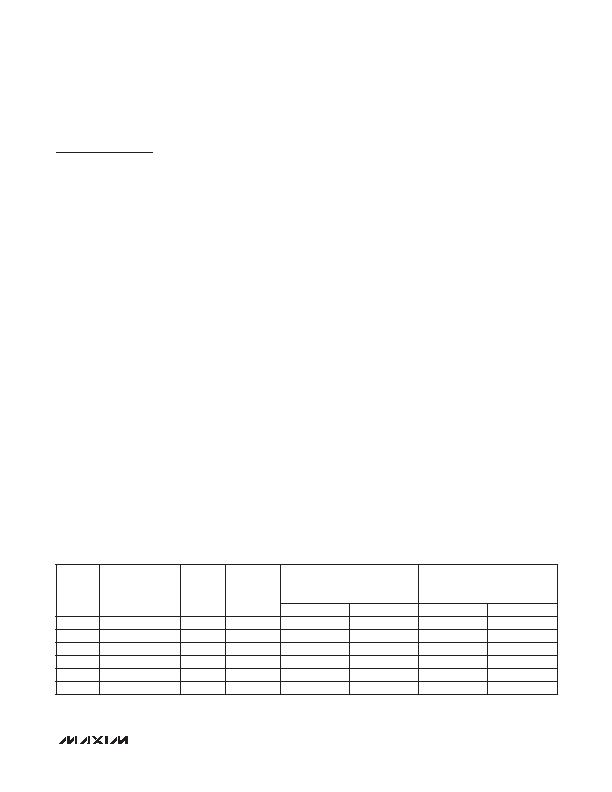
Table 1. Setting Classification Current
*V
IN
is measured across the MAX5981A/MAX5981B input V
DD
to V
SS
.
CLASS
MAXIMUM
POWER USED
BY PD
(W)
R
CLS
(I)
V
IN
*
(V)
CLASS CURRENT SEEN AT
V
IN
(mA)
IEEE 802.3at PD
CLASSIFICATION CURRENT
SPECIFICATION (mA)
MIN
MAX
MIN
MAX
0
0.44 to 12.95
615
12.6 to 20
0
4
0
5
1
0.44 to 3.84
117
12.6 to 20
9
12
8
13
2
3.84 to 6.49
66.5
12.6 to 20
17
20
16
21
3
6.49 to 12.95
43.7
12.6 to 20
26
30
25
31
4
12.95 to 25.5
30.9
12.6 to 20
36
44
35
45
5
> 25.5
21.3
12.6 to 20
54
64
51
68
相关PDF资料 |
PDF描述 |
|---|---|
| VI-2NF-EV-F3 | CONVERTER MOD DC/DC 72V 150W |
| RSC06DRYS | CONN EDGECARD 12POS DIP .100 SLD |
| LC4256C-10T100I | IC PLD 256MC 64I/O 10NS 100TQFP |
| RMC06DRYS | CONN EDGECARD 12POS DIP .100 SLD |
| ACB50DHHT | CONN EDGECARD 100PS .050 DIP SLD |
相关代理商/技术参数 |
参数描述 |
|---|---|
| MAX5981AEVKIT# | 制造商:Maxim Integrated Products 功能描述:EVKIT FOR POWERED DEVICE INTERFACE CONTROLLERS WITH INTEGRAT - Boxed Product (Development Kits) 制造商:Maxim Integrated Products 功能描述:KIT EVAL INTERFACE CONTROLLER |
| MAX5981BETE+ | 功能描述:热插拔功率分布 IEEE 802.3af/at PDIC Controller RoHS:否 制造商:Texas Instruments 产品:Controllers & Switches 电流限制: 电源电压-最大:7 V 电源电压-最小:- 0.3 V 工作温度范围: 功率耗散: 安装风格:SMD/SMT 封装 / 箱体:MSOP-8 封装:Tube |
| MAX5981BETE+T | 功能描述:热插拔功率分布 IEEE 802.3af/at PDIC Controller RoHS:否 制造商:Texas Instruments 产品:Controllers & Switches 电流限制: 电源电压-最大:7 V 电源电压-最小:- 0.3 V 工作温度范围: 功率耗散: 安装风格:SMD/SMT 封装 / 箱体:MSOP-8 封装:Tube |
| MAX5982AETE+ | 功能描述:热插拔功率分布 PDIC, up to 70W RoHS:否 制造商:Texas Instruments 产品:Controllers & Switches 电流限制: 电源电压-最大:7 V 电源电压-最小:- 0.3 V 工作温度范围: 功率耗散: 安装风格:SMD/SMT 封装 / 箱体:MSOP-8 封装:Tube |
| MAX5982AETE+T | 功能描述:热插拔功率分布 PDIC, up to 70W RoHS:否 制造商:Texas Instruments 产品:Controllers & Switches 电流限制: 电源电压-最大:7 V 电源电压-最小:- 0.3 V 工作温度范围: 功率耗散: 安装风格:SMD/SMT 封装 / 箱体:MSOP-8 封装:Tube |
发布紧急采购,3分钟左右您将得到回复。