- 您现在的位置:买卖IC网 > Datasheet目录43 > MAX5986AETE+ (Maxim Integrated)IC POE SWITCH PSE 16TQFN Datasheet资料下载
参数资料
| 型号: | MAX5986AETE+ |
| 厂商: | Maxim Integrated |
| 文件页数: | 12/23页 |
| 文件大小: | 843K |
| 描述: | IC POE SWITCH PSE 16TQFN |
| 标准包装: | 60 |
| 类型: | 以太网供电控制器 PD 开关(PoE) |
| 应用: | 供电设备(PSE) |
| 内部开关: | 是 |
| 电流限制: | 201mA |
| 电源电压: | 8.7 V ~ 60 V |
| 工作温度: | -40°C ~ 85°C |
| 安装类型: | 表面贴装 |
| 封装/外壳: | 16-WQFN 裸露焊盘 |
| 供应商设备封装: | 16-TQFN-EP(5x5) |
| 包装: | 管件 |
MAX5986AMAX5986C/MAX5987A
IEEE 802.3af-Compliant, High-Efficiency, Class 1/
Class 2, PDs with Integrated DC-DC Converter
12
Maxim Integrated
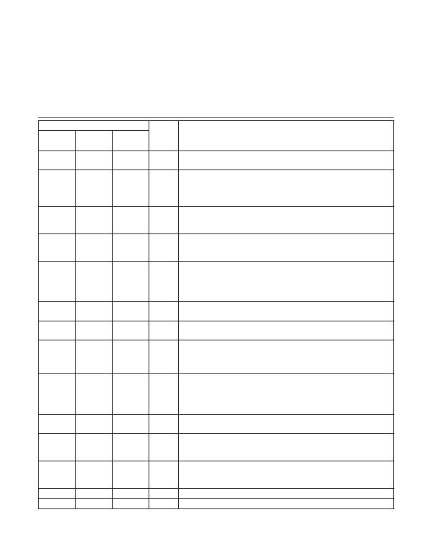
Pin Description (continued)
PIN
NAME
FUNCTION
MAX5986A
MAX5986B/
MAX5986C
MAX5987A
6, 10, 11
6
6
GND
Ground. Reference rail for the device. It is also the
quiet
ground for all
voltage reference (e.g., FB is referenced to this GND).
7
7
7
VDRV
Internal 5V Regulator Voltage Output. The internal voltage regulator provides
5V to the MOSFET driver and other internal circuits. VDRV is referenced to
GND. Do not use VDRV to drive external circuits. Connect a 1FF bypass
capacitor between VDRV and GND.
8
8
SL
Sleep Mode Enable Input. A falling edge on SL brings the device into Sleep
mode. An external resistor (R
SL
) connected between SL and GND sets the
LED current (I
LED
).
8
LDO_
FB
LDO Regulator Feedback Input. Connect to VDRV to get the preset LDO
output voltage of 3.3V, or connect to a resistive divider from the LDO_OUT to
GND for an adjustable LDO output voltage.
9
9
ULP
Ultra-Low Power-Mode Enable Input. ULP has an internal 50kI pullup resistor to
the internal 5V bias rail. A falling edge on SL while ULP is asserted low enables
ultra-low power mode. When ultra-low power mode is enabled, the power
consumption of the device is reduced even lower than sleep mode to comply
with ultra-low power sleep power requirements while still supporting MPS.
10
9
CLASS2
Class 2 Selection Input. Connect to VDRV for Class 2 operation. Connect to
GND for Class 1 operation.
11
10
MPS
MPS Enable Input. Connect to VDRV to turn the MPS function on. Connect to
GND to turn MPS off.
11
RESET
Open-Drain RESET Output. The RESET output is driven low if either LDO_OUT
or FB drops below 90% of its set value. RESET goes high 100Fs after both
LDO_OUT and FB rise above 95% of their set values. Leave unconnected
when not used.
12
12
12
WAD
Wall Power Adapter Detector Input. Wall adapter detection is enabled when
the voltage from WAD to GND is greater than 8.8V. When a wall power
adapter is present, the isolation p-channel power MOSFET turns off. Connect
WAD directly to GND when the wall power adapter or other auxiliary power
source is not used.
13
13
13
V
DD
Positive Supply Input. Connect a 68nF (min) bypass capacitor between V
DD
and PGND.
14
14
14
V
CC
DC-DC Converter Power Input. V
DD
is connected to V
CC
by an isolation
p-channel MOSFET. Connect a 10FF capacitor in parallel with a 1FF ceramic
capacitor between V
CC
and PGND.
15
15
15
PGND
Power Ground. Power ground of the DC-DC converter power stage. Connect
PGND to GND with a star connection. Do not use PGND as reference for
sensitive feedback circuit.
16
16
16
RREF Signature Resistor Connection. Connect a 24.9kI resistor (R
SIG
) to GND.
EP
Exposed Pad. Connect the exposed pad to ground.
相关PDF资料 |
PDF描述 |
|---|---|
| MAX6509CAZK/V+T | IC TEMP SWITCH RES-PROG 5TSOT |
| MAX6513TT075+T | IC TEMP SWITCH REMOTE 6-TDFN |
| MAX6581TG9A+ | IC TEMP SENSOR 8-CH PREC 24-TQFN |
| MAX6602UE9A+T | IC TEMP MONITOR 5CH 16-TSSOP |
| MAX6604ATA+TW | IC TEMP SENSOR DDR MEMORY 8TDFN |
相关代理商/技术参数 |
参数描述 |
|---|---|
| MAX5986AETE+ | 功能描述:直流/直流开关转换器 IEEE802.3 af PD w/ DC/DC Conv RoHS:否 制造商:STMicroelectronics 最大输入电压:4.5 V 开关频率:1.5 MHz 输出电压:4.6 V 输出电流:250 mA 输出端数量:2 最大工作温度:+ 85 C 安装风格:SMD/SMT |
| MAX5986AETE+T | 功能描述:直流/直流开关转换器 IEEE802.3 af PD w/ DC/DC Conv RoHS:否 制造商:STMicroelectronics 最大输入电压:4.5 V 开关频率:1.5 MHz 输出电压:4.6 V 输出电流:250 mA 输出端数量:2 最大工作温度:+ 85 C 安装风格:SMD/SMT |
| MAX5986BETE+ | 功能描述:以太网 IC IEEE802.3 AF HI EFFICIENCY PD RoHS:否 制造商:Micrel 产品:Ethernet Switches 收发器数量:2 数据速率:10 Mb/s, 100 Mb/s 电源电压-最大:1.25 V, 3.45 V 电源电压-最小:1.15 V, 3.15 V 最大工作温度:+ 85 C 封装 / 箱体:QFN-64 封装:Tray |
| MAX5986BETE+T | 功能描述:PMIC 解决方案 IEEE802.3 AF HI EFFICIENCY PD RoHS:否 制造商:Texas Instruments 安装风格:SMD/SMT 封装 / 箱体:QFN-24 封装:Reel |
| MAX5986EVKIT# | 功能描述:电源管理IC开发工具 MAX5986 Eval Kit RoHS:否 制造商:Maxim Integrated 产品:Evaluation Kits 类型:Battery Management 工具用于评估:MAX17710GB 输入电压: 输出电压:1.8 V |
发布紧急采购,3分钟左右您将得到回复。