- 您现在的位置:买卖IC网 > PDF目录180526 > MAX6444US31L+T (MAXIM INTEGRATED PRODUCTS INC) µP Reset Circuits with Long Manual Reset Setup Period PDF资料下载
参数资料
| 型号: | MAX6444US31L+T |
| 厂商: | MAXIM INTEGRATED PRODUCTS INC |
| 元件分类: | 电源管理 |
| 英文描述: | µP Reset Circuits with Long Manual Reset Setup Period |
| 中文描述: | 1-CHANNEL POWER SUPPLY SUPPORT CKT, PDSO4 |
| 封装: | ROHS COMPLIANT, SOT-143, 4 PIN |
| 文件页数: | 10/13页 |
| 文件大小: | 158K |
| 代理商: | MAX6444US31L+T |
MAX6443–MAX6452
P Reset Circuits with Long Manual Reset
Setup Period
6
_______________________________________________________________________________________
Manual Reset Input Options
Unlike typical manual reset functions associated with
supervisors, each device in the MAX6443–MAX6452
family includes at least one manual reset input, which
must be held logic-low for an extended setup period
(tMR) before the RESET output asserts. When valid
manual reset input conditions/setup periods are met,
the RESET output is one-shot pulse asserted low for a
fixed reset timeout period (140ms min). Existing front-
panel pushbutton switches (i.e., power on/off, channel
up/down, or mode select) can be used to drive the
manual reset inputs. The extended manual reset setup
period prevents nuisance system resets during normal
front-panel usage or resulting from inadvertent short-
term pushbutton closure.
The MAX6443/MAX6444, MAX6447/MAX6448, and
MAX6451/MAX6452 include a single manual reset input
with extended setup period (MR1). The MAX6445/
MAX6446 and MAX6449/MAX6450 include two manual
reset inputs (MR1 and MR2) with extended setup peri-
ods. For dual MR1, MR2 devices, both inputs must be
held low simultaneously for the extended setup period
(tMR) before the reset output is pulse asserted. The
dual extended setup provides greater protection from
nuisance resets. (For example, the user or service tech-
nician is informed to simultaneously push both the
on/off button and the channel-select button for 6.72s
(L suffix) to reset the system.)
The MAX6443–MAX6452 RESET output is pulse asserted
once for the reset timeout period after each valid manual
reset input condition. At least one manual reset input
must be released (go high) and then be driven low for the
extended setup period before RESET asserts again.
Internal timing circuitry debounces low-to-high manual
reset logic transitions, so no external circuitry is required.
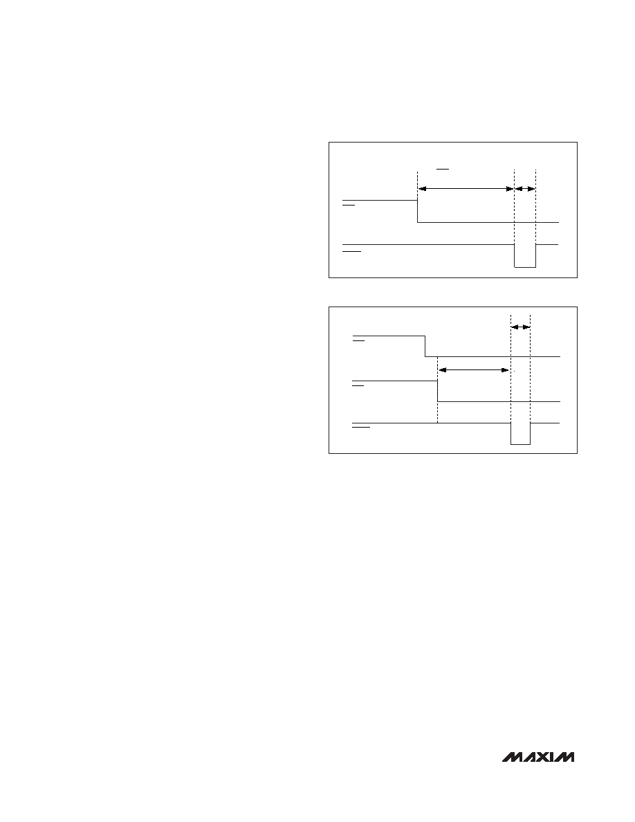
Figure 1 illustrates the single manual reset function of the
MAX6443/MAX6444 single-voltage monitors, and Figure
2 represents the dual manual reset function of the
MAX6445/MAX6446 and MAX6449/MAX6450.
The MAX6447/MAX6448 and MAX6451/MAX6452
include both an extended setup period and immediate
setup period manual reset inputs. A low-to-high MR2
rising edge transition immediately pulse asserts the
RESET output for the reset timeout period (140ms min).
If the MAX6447/MAX6448 and MAX6451/MAX6452
MR2 input senses another rising edge before the end
of the 140ms timeout period (Figure 3), the internal
timer clears and begins counting again. If no rising
edges are detected within the 210ms timeout period,
RESET deasserts. The high-to-low transition on MR2
input is internally debounced for 210ms to ensure that
there are no false RESET assertions when MR2 is dri-
ven from high to low (Figure 4). The MR2 input can be
used for system test purposes or smart-card-detect
applications (see the
Applications Information section).
Adjustable Input Voltage (RSTIN)
The MAX6449–MAX6452 monitor the voltage on RSTIN
using an adjustable reset threshold set with an external
resistor voltage-divider (Figure 5). Use the following for-
mula to calculate the externally monitored voltage
(VMON-TH):
VMON-TH = VTH-RSTIN (R1+ R2)/R2
where VMON-TH is the desired reset threshold voltage
and VTH-RSTIN is the reset input threshold (0.63V).
Resistors R1 and R2 can have very high values to mini-
mize current consumption because of low leakage cur-
rents. Set R2 to some conveniently high value (250k
,
for example), and calculate R1 based on the desired
reset threshold voltage, using the following formula:
R1 = R2 (VMON-TH/VTH-RSTIN - 1)
RESET TIMEOUT PERIOD
210ms
MR1 SETUP PERIOD
tMR
MR1
RESET
Figure 1. MAX6443/MAX6444 Manual Reset Timing Diagram
MR2
RESET
MR1
210ms
tMR
Figure 2. MAX6445/MAX6446/MAX6449/MAX6450 Manual
Reset Timing Diagram
相关PDF资料 |
PDF描述 |
|---|---|
| MAX6444US44L+T | µP Reset Circuits with Long Manual Reset Setup Period |
| MAX6445UK17L+T | µP Reset Circuits with Long Manual Reset Setup Period |
| MAX6445UK22L+T | µP Reset Circuits with Long Manual Reset Setup Period |
| MAX6445UK31L+T | µP Reset Circuits with Long Manual Reset Setup Period |
| MAX6445UK44L+T | µP Reset Circuits with Long Manual Reset Setup Period |
相关代理商/技术参数 |
参数描述 |
|---|---|
| MAX6444US44L | 制造商:Maxim Integrated Products 功能描述:MICROPROCESSOR RESET CIRCUITS WITH - Rail/Tube |
| MAX6444US44L+ | 制造商:Maxim Integrated Products 功能描述:PROCESSOR SUPERVISOR 4.38V 7UA 4PIN SOT-23 - Rail/Tube |
| MAX6444US44L+T | 功能描述:监控电路 Single uPower Reset Circuit RoHS:否 制造商:STMicroelectronics 监测电压数: 监测电压: 欠电压阈值: 过电压阈值: 输出类型:Active Low, Open Drain 人工复位:Resettable 监视器:No Watchdog 电池备用开关:No Backup 上电复位延迟(典型值):10 s 电源电压-最大:5.5 V 最大工作温度:+ 85 C 安装风格:SMD/SMT 封装 / 箱体:UDFN-6 封装:Reel |
| MAX6444US44L-T | 功能描述:监控电路 RoHS:否 制造商:STMicroelectronics 监测电压数: 监测电压: 欠电压阈值: 过电压阈值: 输出类型:Active Low, Open Drain 人工复位:Resettable 监视器:No Watchdog 电池备用开关:No Backup 上电复位延迟(典型值):10 s 电源电压-最大:5.5 V 最大工作温度:+ 85 C 安装风格:SMD/SMT 封装 / 箱体:UDFN-6 封装:Reel |
| MAX6444US46L | 制造商:Maxim Integrated Products 功能描述:MICROPROCESSOR RESET CIRCUITS WITH LONG MANUA - Cut Tape Product |
发布紧急采购,3分钟左右您将得到回复。