- 您现在的位置:买卖IC网 > Datasheet目录44 > MAX6681MEE+ (Maxim Integrated)IC TEMP SENSOR SMBUS 16-QSOP Datasheet资料下载
参数资料
| 型号: | MAX6681MEE+ |
| 厂商: | Maxim Integrated |
| 文件页数: | 8/17页 |
| 文件大小: | 242K |
| 描述: | IC TEMP SENSOR SMBUS 16-QSOP |
| 产品培训模块: | Lead (SnPb) Finish for COTS Obsolescence Mitigation Program |
| 标准包装: | 100 |
| 功能: | 温度计,恒温计 |
| 传感器类型: | 内部和外部 |
| 感应温度: | -55°C ~ 125°C,外部传感器 |
| 精确度: | ±5°C 本地(最大),±3°C 远程(最大) |
| 拓扑: | ADC,多路复用器,寄存器库 |
| 输出类型: | I²C?/SMBus? |
| 输出警报: | 是 |
| 输出风扇: | 是 |
| 电源电压: | 3 V ~ 5.5 V |
| 工作温度: | -55°C ~ 125°C |
| 安装类型: | 表面贴装 |
| 封装/外壳: | 16-SSOP(0.154",3.90mm 宽) |
| 供应商设备封装: | 16-QSOP |
| 包装: | 管件 |
ply hum. In noisy environments, high-frequency noise
reduction is needed for high-accuracy remote mea-
surements. The noise can be reduced with careful PC
board layout and proper external noise filtering.
High-frequency EMI is best filtered at DXP and DXN
with an external 2200pF capacitor. Larger capacitor
values can be used for added filtering, but do not
exceed 3300pF because it can introduce errors due to
the rise time of the switched current source.
PC Board Layout
Follow these guidelines to reduce the measurement
error of the temperature sensors:
1) Place the MAX6680/MAX6681 as close as is practi-
cal to the remote diode. In noisy environments, such
as a computer motherboard, this distance can be
4in to 8in (typ). This length can be increased if the
worst noise sources are avoided. Noise sources
include CRTs, clock generators, memory buses, and
ISA/PCI buses.
2) Do not route the DXP-DXN lines next to the deflec-
tion coils of a CRT. Also, do not route the traces
across fast digital signals, which can easily intro-
duce 30癈 error, even with good filtering.
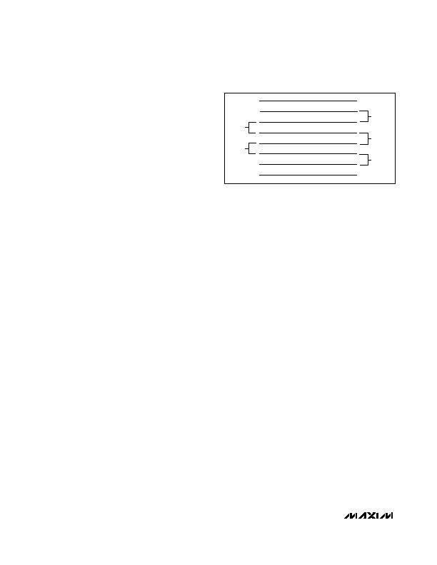
3) Route the DXP and DXN traces in parallel and in
close proximity to each other, away from any higher
voltage traces, such as 12VDC. Leakage currents
from PC board contamination must be dealt with care-
fully since a 20M& leakage path from DXP to ground
causes about 1癈 error. If high-voltage traces are
unavoidable, connect guard traces to GND on either
side of the DXP-DXN traces (Figure 2).
4) Route through as few vias and crossunders as pos-
sible to minimize copper/solder thermocouple
effects.
5) When introducing a thermocouple, make sure that
both the DXP and the DXN paths have matching
thermocouples. A copper-solder thermocouple
exhibits 3礦/癈, and it takes about 200礦 of voltage
error at DXP-DXN to cause a 1癈 measurement
error. Adding a few thermocouples causes a negligi-
ble error.
6) Use wide traces. Narrow traces are more inductive
and tend to pick up radiated noise. The 10mil widths
and spacings that are recommended in Figure 2 are
not absolutely necessary, as they offer only a minor
improvement in leakage and noise over narrow
traces. Use wider traces when practical.
7) Add a 200& resistor in series with V
CC
for best noise
filtering (see the Typical Operating Circuit).
Twisted-Pair and Shielded Cables
Use a twisted-pair cable to connect the remote sensor
for remote-sensor distances longer than 8in or in very
noisy environments. Twisted-pair cable lengths can be
between 6ft and 12ft before noise introduces excessive
errors. For longer distances, the best solution is a
shielded twisted pair like that used for audio micro-
phones. For example, Belden 8451 works well for dis-
tances up to 100ft in a noisy environment. At the
device, connect the twisted pair to DXP and DXN and
the shield to GND. Leave the shield unconnected at the
remote sensor.
For very long cable runs, the cables parasitic capaci-
tance often provides noise filtering, so the 2200pF
capacitor can often be removed or reduced in value.
Cable resistance also affects remote-sensor accuracy.
For every 1& of series resistance, the error is approxi-
mately 1/2癈 error.
Low-Power Standby Mode
Standby mode reduces the supply current to less than
10礎 by disabling the ADC. Enter hardware standby by
forcing the STBY pin low, or enter software standby by
setting the RUN/STOP bit to 1 in the Configuration Byte
register. Hardware and software standbys are very sim-
ilar: all data is retained in memory, and the SMB inter-
face is alive and listening for SMBus commands, but
the SMBus timeout is disabled. The only difference is
that in software standby mode, the One-Shot command
initiates a conversion. With hardware standby, the One-
Shot command is ignored. Activity on the SMBus caus-
es the device to draw extra supply current (see the
Typical Operating Characteristics).
Driving the STBY pin low overrides any software con-
version command. If a hardware or software standby
command is received while a conversion is in progress,
the conversion cycle is interrupted, and the tempera-
?癈 Fail-Safe Remote/Local Temperature
Sensors with SMBus Interface
8 _______________________________________________________________________________________
MINIMUM
10mils
10mils
10mils
10mils
GND
DXN
DXP
GND
Figure 2. Recommended DXP-DXN PC Traces
相关PDF资料 |
PDF描述 |
|---|---|
| MAX6689UP34+ | IC 7CH PREC TEMP MONITOR 20TSSOP |
| MAX6690MEE+ | IC TEMP SENSOR SMBUS 16-QSOP |
| MAX6692YMSA+ | IC SENSOR REMOTE SMBUS 8SOIC |
| MAX6693UP9A+T | IC TEMP MONITOR 7CH 20-TSSOP |
| MAX6694TE9A+T | IC TEMP MONITOR 5CH 16TQFN |
相关代理商/技术参数 |
参数描述 |
|---|---|
| MAX6681MEE+ | 功能描述:板上安装温度传感器 Fail-Safe Temperature Sensor RoHS:否 制造商:Omron Electronics 输出类型:Digital 配置: 准确性:+/- 1.5 C, +/- 3 C 温度阈值: 数字输出 - 总线接口:2-Wire, I2C, SMBus 电源电压-最大:5.5 V 电源电压-最小:4.5 V 最大工作温度:+ 50 C 最小工作温度:0 C 关闭: 安装风格: 封装 / 箱体: 设备功能:Temperature and Humidity Sensor |
| MAX6681MEE+T | 功能描述:板上安装温度传感器 Fail-Safe Temperature Sensor RoHS:否 制造商:Omron Electronics 输出类型:Digital 配置: 准确性:+/- 1.5 C, +/- 3 C 温度阈值: 数字输出 - 总线接口:2-Wire, I2C, SMBus 电源电压-最大:5.5 V 电源电压-最小:4.5 V 最大工作温度:+ 50 C 最小工作温度:0 C 关闭: 安装风格: 封装 / 箱体: 设备功能:Temperature and Humidity Sensor |
| MAX6681MEE-T | 功能描述:板上安装温度传感器 RoHS:否 制造商:Omron Electronics 输出类型:Digital 配置: 准确性:+/- 1.5 C, +/- 3 C 温度阈值: 数字输出 - 总线接口:2-Wire, I2C, SMBus 电源电压-最大:5.5 V 电源电压-最小:4.5 V 最大工作温度:+ 50 C 最小工作温度:0 C 关闭: 安装风格: 封装 / 箱体: 设备功能:Temperature and Humidity Sensor |
| MAX6682MUA | 功能描述:数据转换 IC - 多种 RoHS:否 制造商:Texas Instruments 转换器数量:1 分辨率:8 bit 工作电源电压:2.7 V to 5.5 V 功耗: 工作温度范围:- 40 C to + 85 C 封装 / 箱体:MSOP-10 封装:Reel |
| MAX6682MUA+ | 功能描述:数据转换 IC - 多种 Thermistor to Digital Converter RoHS:否 制造商:Texas Instruments 转换器数量:1 分辨率:8 bit 工作电源电压:2.7 V to 5.5 V 功耗: 工作温度范围:- 40 C to + 85 C 封装 / 箱体:MSOP-10 封装:Reel |
发布紧急采购,3分钟左右您将得到回复。