- 您现在的位置:买卖IC网 > PDF目录20781 > MAX6964AEG+ (Maxim Integrated)IC LED DRIVER LINEAR 24-QSOP PDF资料下载
参数资料
| 型号: | MAX6964AEG+ |
| 厂商: | Maxim Integrated |
| 文件页数: | 16/23页 |
| 文件大小: | 0K |
| 描述: | IC LED DRIVER LINEAR 24-QSOP |
| 产品培训模块: | Lead (SnPb) Finish for COTS Obsolescence Mitigation Program |
| 标准包装: | 50 |
| 拓扑: | 开路漏极,PWM |
| 输出数: | 17 |
| 内部驱动器: | 是 |
| 类型 - 主要: | 背光,LED 闪烁器 |
| 类型 - 次要: | RGB,白色 LED |
| 频率: | 400kHz |
| 电源电压: | 2 V ~ 3.6 V |
| 输出电压: | 7V |
| 安装类型: | 表面贴装 |
| 封装/外壳: | 24-SSOP(0.154",3.90mm 宽) |
| 供应商设备封装: | 24-QSOP |
| 包装: | 管件 |
| 工作温度: | -40°C ~ 125°C |
�� �
�
�17-Output� LED� Driver/GPO� with�
�Intensity� Control� and� Hot-Insertion� Protection�
�For� example,� to� operate� a� 2.2V� red� LED� at� 14mA� from� a�
�5V� supply,� R� LED� =� (5� -� 2.2� -� 0.25)� /� 0.014� =� 182� ?� .�
�2V� TO� 3.6V�
�Driving� Load� Currents� Higher� than� 50mA�
�The� MAX6964� can� be� used� to� drive� loads� drawing�
�0.047� μ� F�
�5V�
�more� than� 50mA,� like� relays� and� high-current� white�
�LEDs,� by� paralleling� outputs.� Use� at� least� one� output�
�per� 50mA� of� load� current;� for� example,� a� 6V� 330mW�
�relay� draws� 55mA� and� needs� two� paralleled� outputs� to�
�drive� it.� Ensure� that� the� paralleled� outputs� chosen� are�
�controlled� by� the� same� blink� phase� register,� i.e.,� select�
�outputs� from� the� O0� through� O7� range,� or� the� O8�
�through� O15� range.� This� way,� the� paralleled� outputs�
�are� turned� on� and� off� together.� Do� not� use� output� O16�
�as� part� of� a� load-sharing� design.� O16� cannot� be�
�μ� C�
�SDA�
�SCL�
�I/O�
�I/O�
�V+�
�SDA�
�SCL�
�BLINK�
�RST�
�AD0�
�MAX6964�
�O0�
�O1�
�O2� MMTBT4148�
�O3�
�O4�
�O5�
�O6�
�O7�
�O8�
�O9�
�switched� at� the� same� time� as� any� of� the� other� outputs�
�because� it� is� controlled� by� a� different� register.�
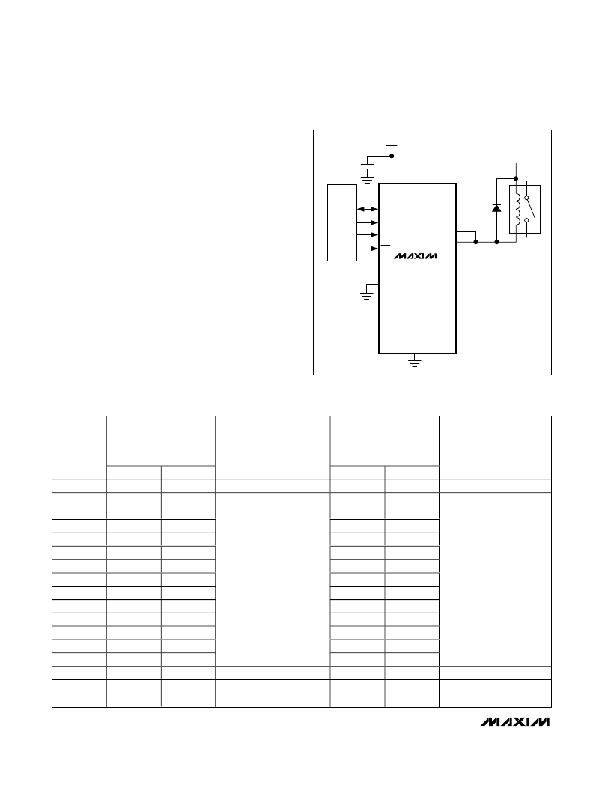
�The� MAX6964� must� be� protected� from� the� negative�
�voltage� transient� generated� when� switching� off� induc-�
�tive� loads,� such� as� relays,� by� connecting� a� reverse-�
�O10�
�O11�
�O12�
�O13�
�O14�
�biased� diode� across� the� inductive� load� (Figure� 19).� The�
�GND�
�O15�
�peak� current� through� the� diode� is� the� inductive� load’s�
�operating� current.�
�Figure� 19.� Diode-Protected� Switching� Inductive� Load�
�Table� 9.� PWM� Intensity� Settings� (Blink� Disabled)�
�OUTPUT�
�(OR�
�GLOBAL)�
�INTENSITY�
�PWM� DUTY� CYCLE�
�OUTPUT� BLINK� PHASE� 0�
�REGISTER� BIT� =� 0�
�LED� BEHAVIOR� WHEN�
�OUTPUT� BLINK� PHASE� 0�
�REGISTER� BIT� =� 0�
�(LED� IS� ON� WHEN�
�PWM� DUTY� CYCLE�
�OUTPUT� BLINK� PHASE� 0�
�REGISTER� =� 1�
�LED� BEHAVIOR� WHEN�
�OUTPUT� BLINK� PHASE� 0�
�REGISTER� BIT� =� 1�
�(LED� IS� ON� WHEN�
�SETTING�
�0x0�
�0x1�
�0x2�
�0x3�
�0x4�
�0x5�
�0x6�
�0x7�
�0x8�
�0x9�
�0xA�
�0xB�
�0xC�
�0xD�
�0xE�
�0xF�
�LOW� TIME�
�1/16�
�2/16�
�3/16�
�4/16�
�5/16�
�6/16�
�7/16�
�8/16�
�9/16�
�10/16�
�11/16�
�12/16�
�13/16�
�14/16�
�15/16�
�Static� low�
�HIGH� TIME�
�15/16�
�14/16�
�13/16�
�12/16�
�11/16�
�10/16�
�9/16�
�8/16�
�7/16�
�6/16�
�5/16�
�4/16�
�3/16�
�2/16�
�1/16�
�Static� low�
�OUTPUT� IS� LOW)�
�Lowest� PWM� intensity�
�Highest� PWM� intensity�
�Full� intensity,� no� PWM�
�(LED� on� continuously)�
�LOW� TIME�
�15/16�
�14/16�
�13/16�
�12/16�
�11/16�
�10/16�
�9/16�
�8/16�
�7/16�
�6/16�
�5/16�
�4/16�
�3/16�
�2/16�
�1/16�
�Static� high�
�impedance�
�HIGH� TIME�
�1/16�
�2/16�
�3/16�
�4/16�
�5/16�
�6/16�
�7/16�
�8/16�
�9/16�
�10/16�
�11/16�
�12/16�
�13/16�
�14/16�
�15/16�
�Static� high�
�impedance�
�OUTPUT� IS� LOW)�
�Highest� PWM� intensity�
�Lowest� PWM� intensity�
�LED� off� continuously�
�16�
�______________________________________________________________________________________�
�相关PDF资料 |
PDF描述 |
|---|---|
| MAX6968APE+ | IC LED DRIVER LINEAR 16-DIP |
| MAX6971ANG+ | IC LED DRIVER LINEAR 24-DIP |
| ECC08DRES | CONN EDGECARD 16POS .100 EYELET |
| MAX16832CASA+ | IC LED DRIVER HIGH BRIGHT 8-SOIC |
| MAX16832AASA+ | IC LED DRIVER HIGH BRIGHT 8-SOIC |
相关代理商/技术参数 |
参数描述 |
|---|---|
| MAX6964AEG+ | 功能描述:LED显示驱动器 17-Output LED Driver/GPO RoHS:否 制造商:Micrel 数位数量:5 片段数量: 安装风格:SMD/SMT 封装 / 箱体:PLCC-44 工作电源电压:4.75 V to 11 V 最大电源电流:10 mA 最大工作温度:+ 85 C 最小工作温度:- 40 C 封装:Tube |
| MAX6964AEG+T | 功能描述:LED显示驱动器 17-Output LED Driver/GPO RoHS:否 制造商:Micrel 数位数量:5 片段数量: 安装风格:SMD/SMT 封装 / 箱体:PLCC-44 工作电源电压:4.75 V to 11 V 最大电源电流:10 mA 最大工作温度:+ 85 C 最小工作温度:- 40 C 封装:Tube |
| MAX6964AEG-T | 功能描述:LED显示驱动器 17-Output LED Driver/GPO RoHS:否 制造商:Micrel 数位数量:5 片段数量: 安装风格:SMD/SMT 封装 / 箱体:PLCC-44 工作电源电压:4.75 V to 11 V 最大电源电流:10 mA 最大工作温度:+ 85 C 最小工作温度:- 40 C 封装:Tube |
| MAX6964ATG | 功能描述:LED显示驱动器 17-Output LED Driver/GPO RoHS:否 制造商:Micrel 数位数量:5 片段数量: 安装风格:SMD/SMT 封装 / 箱体:PLCC-44 工作电源电压:4.75 V to 11 V 最大电源电流:10 mA 最大工作温度:+ 85 C 最小工作温度:- 40 C 封装:Tube |
| MAX6964ATG+ | 功能描述:LED显示驱动器 17-Output LED Driver/GPO RoHS:否 制造商:Micrel 数位数量:5 片段数量: 安装风格:SMD/SMT 封装 / 箱体:PLCC-44 工作电源电压:4.75 V to 11 V 最大电源电流:10 mA 最大工作温度:+ 85 C 最小工作温度:- 40 C 封装:Tube |
发布紧急采购,3分钟左右您将得到回复。