- 您现在的位置:买卖IC网 > PDF目录18708 > MAX7033EVKIT-433 (Maxim Integrated)EVAL KIT FOR MAX7033 433MHZ PDF资料下载
参数资料
| 型号: | MAX7033EVKIT-433 |
| 厂商: | Maxim Integrated |
| 文件页数: | 4/7页 |
| 文件大小: | 0K |
| 描述: | EVAL KIT FOR MAX7033 433MHZ |
| 其它有关文件: | Automotive Product Guide |
| 产品培训模块: | Lead (SnPb) Finish for COTS Obsolescence Mitigation Program |
| 标准包装: | 1 |
| 类型: | 接收器,ASK |
| 频率: | 433MHz |
| 适用于相关产品: | MAX7033 433MHz |
| 已供物品: | 板 |
�� �
�
�MAX7033� Evaluation� Kit�
�Power� Supply�
�The� MAX7033� can� operate� from� 3.3V� or� 5V� supplies.�
�For� 5V� operation,� remove� JU7� before� connecting� the�
�supply� to� VDD.� For� 3.3V� operation,� connect� JU7.�
�IF� Input/Output�
�The� 10.7MHz� IF� can� be� monitored� with� the� help� of� a�
�spectrum� analyzer� using� the� MIX_OUT� SMA� (not� provid-�
�Test� Points� and� I/O� Connections�
�Additional� test� points� and� I/O� connectors� are� provided�
�to� monitor� the� various� baseband� signals� and� for� exter-�
�nal� connections.� See� Tables� 2� and� 3� for� a� description.�
�For� additional� information� and� a� list� of� application�
�notes,� visit� www.maxim-ic.com.�
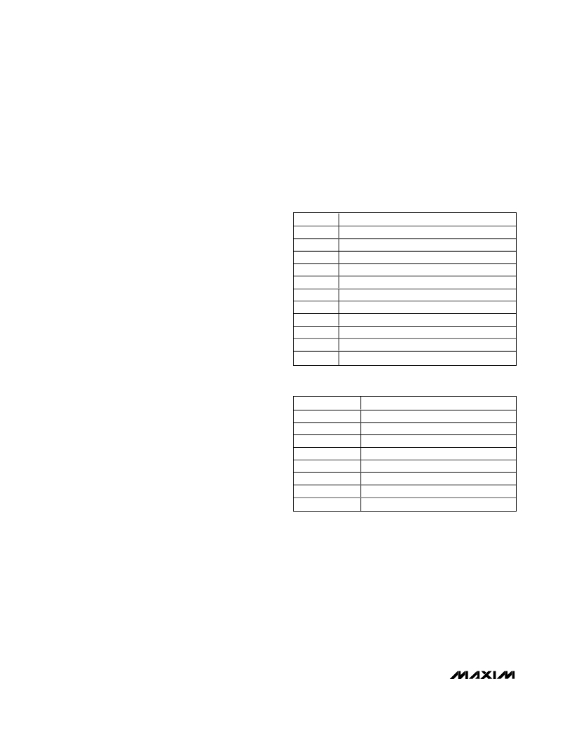
�Table� 2.� Test� Points�
�ed).� Remove� the� ceramic� filter� for� such� a� measurement�
�and� include� R3� (270� ?� )� and� C17� (0.01μF)� to� match� the�
�330� ?� mixer� output� with� the� 50� ?� spectrum� analyzer.�
�Jumper� JU3� needs� to� connect� pins� 1� and� 2.� It� is� also�
�possible� to� use� the� MIX_OUT� SMA� to� inject� an� external�
�IF� as� a� means� of� evaluating� the� baseband� data� slicing�
�section.� Jumper� JU3� needs� to� connect� pins� 2� and� 3.�
�F_IN� External� Frequency� Input�
�For� applications� where� the� correct� frequency� crystal� is�
�not� available,� it� is� possible� to� directly� inject� an� external�
�frequency� through� the� F_IN� SMA� (not� provided).�
�Connect� the� SMA� to� a� function� generator.� The� addition�
�of� C18� and� C19� is� necessary� (use� 0.01μF� capacitors).�
�AGC� Control�
�Jumper� JU5� controls� whether� the� AGC� is� enabled.�
�Connect� pins� 2� and� 3� to� enable� the� AGC.� In� addition,�
�TP�
�2�
�3�
�4�
�5�
�6�
�7�
�8�
�9�
�10�
�11�
�12�
�DESCRIPTION�
�Data� slicer� negative� input�
�Data� filter� output�
�Peak� detector� out�
�+3.3V�
�GND�
�Data� filter� feedback� node�
�Data� out�
�Power-down� select� input�
�VDD�
�AGC� control�
�Crystal� select�
�by� removing� the� jumper,� the� AGC� setting� can� be�
�Table� 3.� I/O� Connectors�
�locked� or� unlocked� by� transitioning� the� AC� pin� while� the�
�SHDN� pin� is� high.�
�Crystal� Select�
�Jumper� JU2� controls� the� crystal-divide� ratio.�
�Connecting� pins� 1� and� 2� sets� the� divide� ratio� to� 32,�
�while� connecting� pins� 2� and� 3� sets� the� ratio� to� 64.� This�
�determines� the� frequency� of� the� crystal� to� be� used.�
�Image-Rejection� Frequency� Select�
�A� unique� feature� of� the� MAX7033� is� its� ability� to� vary� at�
�which� frequency� the� image� rejection� is� optimized.� JU6�
�allows� the� selection� of� three� possible� frequencies:�
�315MHz,� 375MHz,� and� 433.92MHz.� See� Table� 1�
�for� settings.�
�SIGNAL�
�RF_IN�
�F_IN�
�MIX_OUT�
�GND�
�VDD�
�DATA_OUT�
�SHDN�
�AGC_C�
�DESCRIPTION�
�RF� input�
�External� reference� frequency� input�
�IF� input/output�
�Ground�
�Supply� input�
�Sliced� data� output�
�External� power-down� control�
�AGC� control�
�4�
�_______________________________________________________________________________________�
�相关PDF资料 |
PDF描述 |
|---|---|
| GLAC06C | SWITCH ROLLER PLUNGER SLOW 2NC |
| TC70V6A32K7680 | OSCILLATOR 32.7680 KHZ 1.5V SMD |
| TC70M6A32K7680 | OSCILLATOR 32.7680 KHZ 1.8V SMD |
| MAX2045EVKIT | EVAL KIT FOR MAX2045 |
| MAX2046EVKIT | EVAL KIT FOR MAX2046 |
相关代理商/技术参数 |
参数描述 |
|---|---|
| MAX7034 | 制造商:MAXIM 制造商全称:Maxim Integrated Products 功能描述:315MHz/434MHz ASK Superheterodyne Receiver |
| MAX7034_09 | 制造商:MAXIM 制造商全称:Maxim Integrated Products 功能描述:315MHz/434MHz ASK Superheterodyne Receiver |
| MAX7034_11 | 制造商:MAXIM 制造商全称:Maxim Integrated Products 功能描述:315MHz/434MHz ASK Superheterodyne Receiver 250μs Startup Time |
| MAX7034_1206 | 制造商:MAXIM 制造商全称:Maxim Integrated Products 功能描述:315MHz/434MHz ASK Superheterodyne Receiver |
| MAX7034AUI | 制造商:MAXIM 制造商全称:Maxim Integrated Products 功能描述:315MHz/434MHz ASK Superheterodyne Receiver 250μs Startup Time |
发布紧急采购,3分钟左右您将得到回复。