- 您现在的位置:买卖IC网 > PDF目录16560 > MAX749ESA+T (Maxim Integrated Products)IC SUPPLY LCD BIAS ADJ 8-SOIC PDF资料下载
参数资料
| 型号: | MAX749ESA+T |
| 厂商: | Maxim Integrated Products |
| 文件页数: | 8/12页 |
| 文件大小: | 0K |
| 描述: | IC SUPPLY LCD BIAS ADJ 8-SOIC |
| 产品培训模块: | Lead (SnPb) Finish for COTS Obsolescence Mitigation Program |
| 标准包装: | 2,500 |
| 应用: | LCD 显示器 |
| 电流 - 电源: | 60µA |
| 电源电压: | 2 V ~ 6 V |
| 工作温度: | -40°C ~ 85°C |
| 安装类型: | 表面贴装 |
| 封装/外壳: | 8-SOIC(0.154",3.90mm 宽) |
| 供应商设备封装: | 8-SOIC |
| 包装: | 带卷 (TR) |
�� �
�
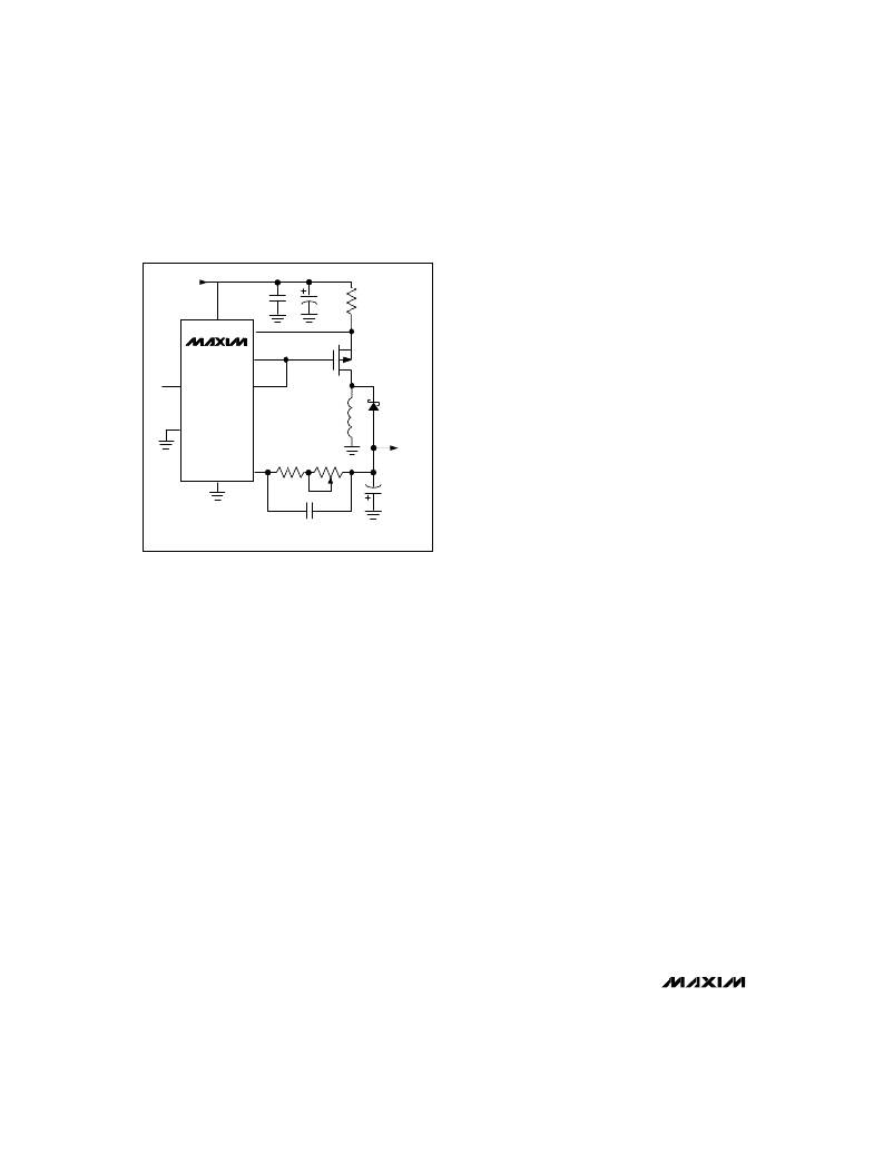
�Digitally� Adjustable� LCD� Bias� Supply�
�Current-Sense� Resistor�
�+4.5V� to� +6V�
�INPUT�
�0.1� μ� F�
�V+�
�CS�
�MAX749� DHI�
�22� μ� F�
�R� SENSE�
�Q1�
�SMD10P05L�
�The� current-sense� resistor� limits� the� peak� switch� cur-�
�rent� to� 140mV/R� SENSE� ,� where� R� SENSE� is� the� value� of� the�
�current-sense� resistor,� and� 140mV� is� the� typical� cur-�
�rent-sense� comparator� threshold� (see� V+� to� CS� Voltage�
�in� the� Electrical� Characteristics).�
�To� maximize� efficiency� and� reduce� the� size� and� cost� of�
�the� external� components,� minimize� the� peak� current.�
�CTRL�
�DLOW�
�However,� since� the� output� current� is� a� function� of� the� peak�
�current� (Figures� 9a-9e),� the� limit� should� not� be� set� too� low.�
�ADJ�
�L1�
�47� μ� H�
�D1�
�1N5819�
�No� calculations� are� required� to� choose� the� proper� cur-�
�rent-sense� resistor;� simply� follow� this� two-step� procedure:�
�1.� Determine:�
�GND�
�R1�
�R2�
�V� OUT�
�(NEGATIVE)�
�-� the� minimum� input� voltage,� V� IN(MIN),�
�-� the� maximum� output� voltage,� V� OUT(MAX)� ,� and�
�-� the� maximum� output� current,� I� OUT(MAX)� .�
�22� μ� F�
�For� example,� assume� that� the� output� voltage� must� be�
�V� OUT(MIN)� =� -R1(13.33� μ� A)�
�V� OUT(MAX)� =� -(R1+R2)(13.33� μ� A)�
�C� COMP�
�30V�
�adjustable� to� -24V� (V� OUT(MAX)� =� -24V)� at� up� to� 30mA�
�(I� OUT(MAX)� =� 30mA).� The� supply� voltage� ranges� from�
�4.75V� to� 6V� (V� IN(MIN)� =� 4.75V).�
�Figure� 8.� Using� a� Potentiometer� to� Adjust� the� Output� Voltage�
�counter� rolls� over� and� sets� the� DAC� to� -V� OUT(MIN)� ,�
�where� -V� OUT(MIN)� =� R� FB� x� 6.66μA.� In� other� words,� a� sin-�
�gle� rising� edge� of� ADJ� increments� the� DAC� output� by�
�one,� and� 63� rising� edges� of� ADJ� decrement� the� DAC�
�output� by� one.�
�Potentiometer� Adjustment�
�It� is� also� possible� to� adjust� the� output� voltage� using� a�
�potentiometer� instead� of� the� internal� DAC� (Figure� 8).� On�
�power-up� (V+� applied),� the� internal� current� source� is� set�
�to� mid-scale,� or� 13.33μA.� Choose� R1� and� R2� with� the� fol-�
�lowing� equations:�
�R1� =� -V� OUT(MIN)� /13.33μA�
�R2� =� -V� OUT(MAX)� /13.33μA� -� R1.�
�Where� the� potentiometer� can� be� varied� from� 0� (producing�
�V� OUT(MIN)� )� to� R2� ?� (producing� V� OUT(MAX)� ).� Notice� that� ADJ�
�is� connected� to� ground,� allowing� the� device� to� be� shut�
�down.�
�PWM� Adjustment�
�A� positive� pulse-width� modulated� (PWM)� logic� signal�
�(e.g.,� from� a� microcontroller)� can� control� the� MAX749’s�
�output� voltage.� Use� the� PWM� signal� to� pull� up� the� FB�
�pin� through� a� suitable� resistor.� An� RC� network� on� the�
�PWM� output� would� also� be� required.� In� this� configura-�
�tion,� the� longer� the� PWM� signal� remains� high,� the� more�
�negative� the� MAX749’s� output� will� be� driven.�
�2.� In� Figures� 9a-9e,� locate� the� graph� drawn� for� the�
�appropriate� output� voltage� (which� is� either� the�
�desired� output� voltage� or,� if� that� is� not� shown,� the�
�graph� for� the� nearest� voltage� more� negative� than� the�
�desired� output).� On� this� graph� find� the� curve� for� the�
�highest� R� SENSE� (the� lowest� current� limit)� with� an� out-�
�put� current� that� is� adequate� at� the� lowest� input�
�voltage.�
�In� this� example,� select� the� -24V� output� graph,� Figure� 9d.�
�We� then� want� a� curve� where� I� OUT� is� ≥� 30mA� with� a� 4.75V�
�input.� The� 0.3� ?� R� SENSE� graph� shows� 25mA� of� output� cur-�
�rent� with� a� 4.75V� input,� so� we� look� next� at� the� 0.25� ?�
�R� SENSE� graph.� It� shows� I� OUT� =� 30mA� for� V� IN� =� 4.75V� and�
�V� OUT� =� -24V.� Therefore� select� R� SENSE� =� 0.25� ?� .� This� pro-�
�vides� a� current� limit� in� the� range� 440mA� to� 720mA.�
�Alternatively,� a� 0.2� ?� sense� resistor� can� be� used.� This�
�gives� a� current� limit� in� the� range� 550mA� to� 900mA,� but�
�enables� over� 40mA� to� be� generated� at� -24V� with� input�
�voltages� down� to� 4.5V.� A� 0.2� ?� resistor� may� be� easier� to�
�obtain� than� an� 0.25� ?� resistor.�
�The� theoretical� design� curves� shown� in� Figures� 9a-9e�
�assume� the� minimum� (worst-case)� value� for� the� current-�
�limit� comparator� threshold.� Having� selected� the� cur-�
�rent-sense� resistor,� the� maximum� current� limit� is� given�
�by� 180mV/R� SENSE� .� Use� the� maximum� current-limit� fig-�
�ure� when� choosing� the� transistor,� coil,� and� diode.�
�IRC� (see� Table� 2)� makes� surface-mount� resistors� with� pre-�
�ferred� values� including:� 0.1� ?� ,� 0.2� ?� ,� 0.3� ?� ,� 0.5� ?� ,� and� 1.0� ?� .�
�8�
�______________________________________________________________________________________�
�相关PDF资料 |
PDF描述 |
|---|---|
| RSA06DRSN-S288 | CONN EDGECARD 12POS .125 EXTEND |
| H3CCS-6406M | IDC CABLE - HKC64S/AE64M/HKC64S |
| UPC3218GV-EVAL | EVAL BOARD FOR UPC3218GV |
| M2MXH-2020K | IDC CABLE - MDM20H/MC20F/X |
| GBC19DRES-S734 | CONN EDGECARD 38POS .100 EYELET |
相关代理商/技术参数 |
参数描述 |
|---|---|
| MAX749ESA-TG074 | 制造商:Maxim Integrated Products 功能描述:DIGITALLY ADJUSTABLE LCD BIAS SUPPLY - Rail/Tube |
| MAX749EVKIT-SO | 功能描述:显示开发工具 RoHS:否 制造商:4D Systems 产品:4Display Shields 工具用于评估:?OLED-160-G1, ?OLED-160-G2 接口类型:Serial 工作电源电压:5 V |
| MAX-750 | 制造商:SLPOWER 制造商全称:SL Power Electronics 功能描述:MAX-750 Multiple Output |
| MAX7500EVKIT+ | 功能描述:板上安装温度传感器 MAX7500 Eval Kit RoHS:否 制造商:Omron Electronics 输出类型:Digital 配置: 准确性:+/- 1.5 C, +/- 3 C 温度阈值: 数字输出 - 总线接口:2-Wire, I2C, SMBus 电源电压-最大:5.5 V 电源电压-最小:4.5 V 最大工作温度:+ 50 C 最小工作温度:0 C 关闭: 安装风格: 封装 / 箱体: 设备功能:Temperature and Humidity Sensor |
| MAX7500MSA | 功能描述:板上安装温度传感器 RoHS:否 制造商:Omron Electronics 输出类型:Digital 配置: 准确性:+/- 1.5 C, +/- 3 C 温度阈值: 数字输出 - 总线接口:2-Wire, I2C, SMBus 电源电压-最大:5.5 V 电源电压-最小:4.5 V 最大工作温度:+ 50 C 最小工作温度:0 C 关闭: 安装风格: 封装 / 箱体: 设备功能:Temperature and Humidity Sensor |
发布紧急采购,3分钟左右您将得到回复。