- 您现在的位置:买卖IC网 > PDF目录13527 > MAX758AEWE+T (Maxim Integrated Products)IC REG BUCK ADJ 0.75A 16SOIC PDF资料下载
参数资料
| 型号: | MAX758AEWE+T |
| 厂商: | Maxim Integrated Products |
| 文件页数: | 7/16页 |
| 文件大小: | 0K |
| 描述: | IC REG BUCK ADJ 0.75A 16SOIC |
| 产品培训模块: | Lead (SnPb) Finish for COTS Obsolescence Mitigation Program |
| 标准包装: | 1,000 |
| 类型: | 降压(降压) |
| 输出类型: | 可调式 |
| 输出数: | 1 |
| 输出电压: | 1.25 V ~ 16 V |
| 输入电压: | 4 V ~ 16 V |
| PWM 型: | 电流模式 |
| 频率 - 开关: | 160kHz |
| 电流 - 输出: | 750mA |
| 同步整流器: | 无 |
| 工作温度: | -40°C ~ 85°C |
| 安装类型: | 表面贴装 |
| 封装/外壳: | 16-SOIC(0.295",7.50mm 宽) |
| 包装: | 带卷 (TR) |
| 供应商设备封装: | 16-SOIC W |
�� �
�
�Adjustable,� Step-Down,�
�Current-Mode� PWM� Regulators�
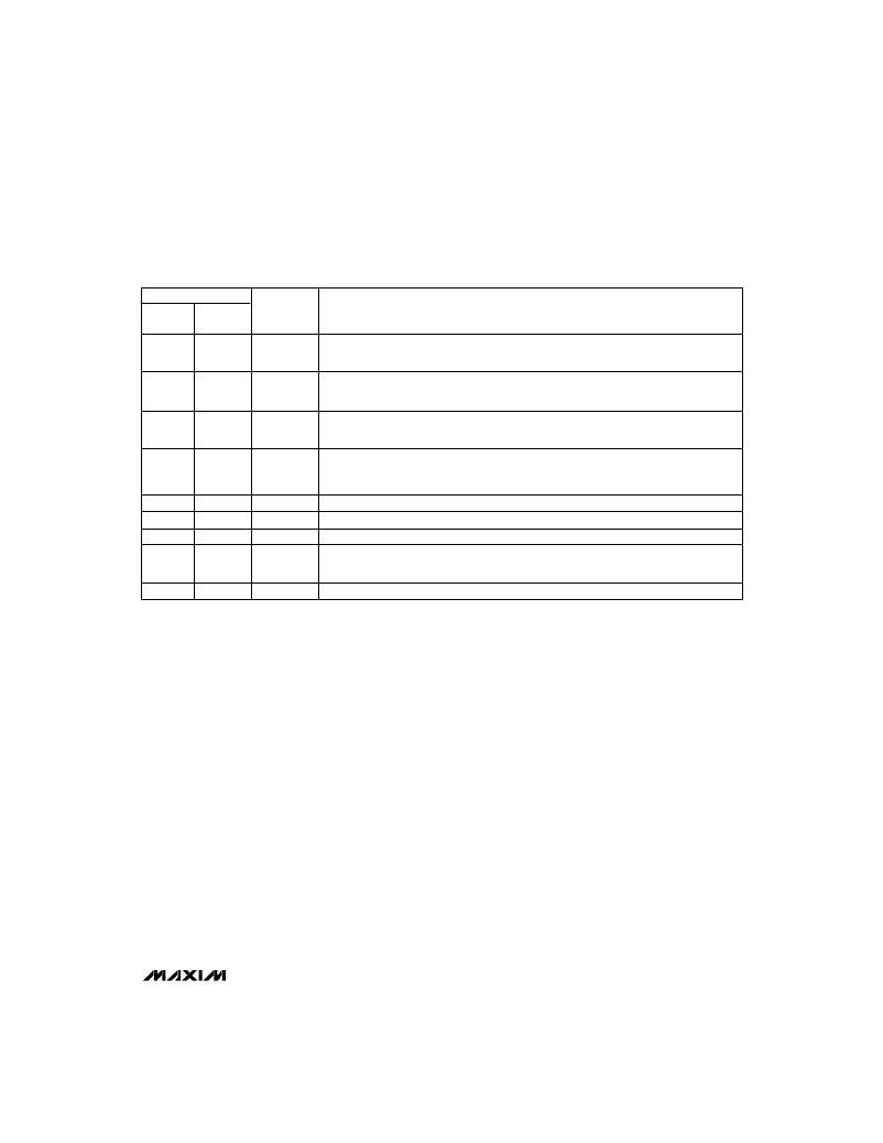
�______________________________________________________________Pin� Description�
�PIN�
�8-PIN�
�DIP/SO�
�1�
�2�
�3�
�16-PIN�
�WIDE� SO�
�2�
�3�
�7�
�NAME�
�SHDN�
�REF�
�SS�
�FUNCTION�
�Shutdown—active� low.� Ground� to� power-down� chip,� tie� to� V+� for� normal� operation.�
�Output� voltage� falls� to� 0V� when� SHDN� is� low.�
�Reference� Voltage� Output� (+1.22V)� supplies� up� to� 100μA� for� external� loads.� Bypass� to�
�GND� with� a� capacitor� that� does� not� exceed� 0.047μF.�
�Soft-Start.� Capacitor� between� SS� and� GND� provides� soft-start� and� short-circuit� protec-�
�tion.� 510k� ?� resistor� from� SS� to� SHDN� provides� current� boost.�
�External� voltage� divider� feedback� point.� When� an� external� voltage� divider� is� connected� from�
�4�
�8�
�CC�
�the� output� voltage� to� CC� and� GND,� this� pin� becomes� the� feedback� input� for� adjusting� the�
�output� voltage.� Connect� a� 330pF� compensation� capacitor� between� the� output� and� CC.�
�5�
�6�
�7�
�8�
�–�
�9�
�10,� 11�
�12,� 13,� 14�
�1,� 15,� 16�
�4,� 5,� 6�
�I.C.�
�GND�
�LX�
�V+�
�N.C.�
�Internal� Connection.� Make� no� external� connection� to� this� pin.�
�Ground*�
�Drain� of� internal� P-channel� power� MOSFET*�
�Supply� Voltage� Input.� Bypass� to� GND� with� 1.0μF� ceramic� and� large-value� electrolytic� capaci-�
�tors� in� parallel.� The� 1μF� capacitor� must� be� as� close� to� the� V+� and� GND� pins� are� possible.*�
�No� Connect—not� internally� connected.�
�*16-Pin� Wide� SO:� All� pins� with� the� same� name� must� be� connected� together� externally.�
�_______________Detailed� Description�
�The� MAX750A/MAX758A� switch-mode� regulators� use� a�
�current-mode� pulse-width-modulation� (PWM)� control�
�system� coupled� with� a� simple� step-down� (buck)� regula-�
�tor� topography.� Input� voltages� range� from� 4V� to� 11V� for�
�the� MAX750A,� and� from� 4V� to� 16V� for� the� MAX758A.�
�The� current-mode� PWM� architecture� provides� cycle-by-�
�cycle� current� limiting,� improved� load� transient� response�
�characteristics,� and� simpler� outer-loop� design.�
�The� controller� consists� of� two� feedback� loops:� an� inner�
�(current)� loop� that� monitors� the� switch� current� via� the�
�current-sense� resistor� and� amplifier,� and� an� outer� (volt-�
�age)� loop� that� monitors� the� output� voltage� through� the�
�error� amplifier� (Figure� 1).� The� inner� loop� performs�
�cycle-by-cycle� current� limiting,� truncating� the� power-�
�transistor� on-time� when� the� switch� current� reaches� a�
�predetermined� threshold.� This� threshold� is� determined�
�by� the� outer� loop.� For� example,� a� sagging� output� volt-�
�age� produces� an� error� signal� that� raises� the� threshold,�
�allowing� the� circuit� to� store� and� transfer� more� energy�
�during� each� cycle.�
�Programmable� Soft-Start�
�Figures� 1� and� 2� show� a� capacitor� and� a� resistor� connect-�
�ed� to� the� soft-start� (SS)� pin� to� ensure� an� orderly� power-�
�up.� Typical� values� are� 0.1μF� and� 510k� ?� .� SS� controls�
�both� the� soft-start� timing� and� the� maximum� output� cur-�
�rent� that� can� be� delivered� while� maintaining� regulation.�
�The� charging� capacitor� slowly� raises� the� clamp� on� the�
�error-amplifier� output� voltage,� limiting� surge� currents� at�
�power-up� by� slowly� increasing� the� cycle-by-cycle� current-�
�limit� threshold.� The� 510k� ?� resistor� sets� the� soft-start�
�clamp� at� a� value� high� enough� to� maintain� regulation,� even�
�at� currents� exceeding� 1A.� This� resistor� is� not� necessary�
�for� lower� current� loads.� Refer� to� the� Maximum� Output�
�Current� vs.� Supply� Voltage,� No.� R1� graph� in� the� Typical�
�Operating� Characteristics.� Table� 1� lists� timing� character-�
�istics� for� selected� capacitor� values� and� circuit� conditions.�
�The� overcurrent� comparator� trips� if� the� load� exceeds�
�approximately� 1.5A.� A� soft-start� cycle� begins� when�
�either� an� undervoltage� or� overcurrent� fault� condition�
�triggers� an� internal� transistor� to� discharge� the� soft-�
�start� capacitor� to� ground.� A� soft-start� cycle� also�
�begins� at� power-up� and� when� coming� out� of� the� shut-�
�down� mode.�
�_______________________________________________________________________________________�
�7�
�相关PDF资料 |
PDF描述 |
|---|---|
| HBC12DREH-S734 | CONN EDGECARD 24POS .100 EYELET |
| MAX748AEWE+T | IC REG BUCK 3.3V 0.5A 16SOIC |
| GEC36DRYN-S734 | CONN EDGECARD 72POS DIP .100 SLD |
| VI-2NF-EX-F3 | CONVERTER MOD DC/DC 72V 75W |
| VI-2NF-EX-F1 | CONVERTER MOD DC/DC 72V 75W |
相关代理商/技术参数 |
参数描述 |
|---|---|
| MAX758AMJA | 功能描述:直流/直流开关调节器 RoHS:否 制造商:International Rectifier 最大输入电压:21 V 开关频率:1.5 MHz 输出电压:0.5 V to 0.86 V 输出电流:4 A 输出端数量: 最大工作温度: 安装风格:SMD/SMT 封装 / 箱体:PQFN 4 x 5 |
| MAX758C/D DIE | 制造商:Maxim Integrated Products 功能描述: |
| MAX758CPA | 功能描述:直流/直流开关调节器 RoHS:否 制造商:International Rectifier 最大输入电压:21 V 开关频率:1.5 MHz 输出电压:0.5 V to 0.86 V 输出电流:4 A 输出端数量: 最大工作温度: 安装风格:SMD/SMT 封装 / 箱体:PQFN 4 x 5 |
| MAX758CWE | 功能描述:直流/直流开关调节器 RoHS:否 制造商:International Rectifier 最大输入电压:21 V 开关频率:1.5 MHz 输出电压:0.5 V to 0.86 V 输出电流:4 A 输出端数量: 最大工作温度: 安装风格:SMD/SMT 封装 / 箱体:PQFN 4 x 5 |
| MAX758CWE-T | 功能描述:直流/直流开关调节器 RoHS:否 制造商:International Rectifier 最大输入电压:21 V 开关频率:1.5 MHz 输出电压:0.5 V to 0.86 V 输出电流:4 A 输出端数量: 最大工作温度: 安装风格:SMD/SMT 封装 / 箱体:PQFN 4 x 5 |
发布紧急采购,3分钟左右您将得到回复。