- 您现在的位置:买卖IC网 > PDF目录13244 > MAX762EPA+ (Maxim Integrated Products)IC REG BOOST 15V/ADJ 0.15A 8DIP PDF资料下载
参数资料
| 型号: | MAX762EPA+ |
| 厂商: | Maxim Integrated Products |
| 文件页数: | 10/12页 |
| 文件大小: | 0K |
| 描述: | IC REG BOOST 15V/ADJ 0.15A 8DIP |
| 标准包装: | 50 |
| 类型: | 升压(升压) |
| 输出类型: | 两者兼有 |
| 输出数: | 1 |
| 输出电压: | 15V,5 V ~ 16.5 V |
| 输入电压: | 2 V ~ 16.5 V |
| 频率 - 开关: | 300kHz |
| 电流 - 输出: | 150mA |
| 同步整流器: | 无 |
| 工作温度: | -40°C ~ 85°C |
| 安装类型: | 通孔 |
| 封装/外壳: | 8-DIP(0.300",7.62mm) |
| 包装: | 管件 |
| 供应商设备封装: | 8-PDIP |
�� �
�
�12V/15V� or� Adjustable,� High-Efficiency,�
�Low� I� Q� ,� Step-Up� DC-DC� Converters�
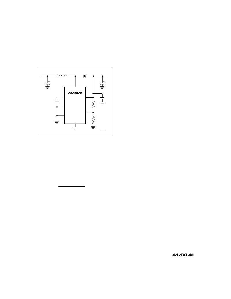
�V� IN�
�L1�
�18μH�
�D1�
�1N5817�
�V� OUT�
�Inductors� with� a� ferrite� core� or� equivalent� are� recom-�
�mended.� The� inductor’s� incremental� saturation-current�
�rating� should� be� greater� than� the� 1A� peak� current� limit.� It�
�is� generally� acceptable� to� bias� the� inductor� into� satura-�
�C1�
�LX�
�7�
�C4�
�tion� by� approximately� 20%� (the� point� where� the� induc-�
�tance� is� 20%� below� the� nominal� value).� For� highest� effi-�
�ciency,� use� a� coil� with� low� DC� resistance,� preferably�
�under� 100m� ?� .� To� minimize� radiated� noise,� use� a� toroid,�
�C3�
�5�
�REF�
�MAX761�
�MAX762�
�V+�
�8�
�C2�
�a� pot� core,� or� a� shielded� coil.�
�Table� 1� lists� inductor� types� and� suppliers� for� various�
�2�
�LBI�
�R2�
�applications.� The� listed� surface-mount� inductors’� efficien-�
�cies� are� nearly� equivalent� to� those� of� the� larger� through-�
�4�
�SHDN�
�FB�
�3�
�hole� inductors.�
�Diode� Selection�
�C1� =� 33μF�
�C2� =� 0.1μF�
�C3� =� 0.1μF�
�C4� =� 33μF�
�GND�
�6�
�V� REF� =� 1.5V� NOMINAL�
�R1�
�R2� =� R1�
�REF�
�(� V OUT� -1� )�
�The� MAX761/MAX762� ’s� high� switching� frequency�
�demands� a� high-speed� rectifier.� Use� a� Schottky� diode�
�with� a� 1A� average� current� rating,� such� as� a� 1N5817.� For�
�high-temperature� applications,� use� a� high-speed� silicon�
�diode,� such� as� the� MUR105� or� the� EC11FS1.� These�
�Figure� 5.� Bootstrapped� Operation� with� Adjustable� Output�
�Selecting� the� Inductor� (L)�
�In� both� CCM� and� DCM,� practical� inductor� values� range�
�from� 10μH� to� 50μH.� If� the� inductor� value� is� too� low,� the�
�current� in� the� coil� will� ramp� up� to� a� high� level� before� the�
�current-limit� comparator� can� turn� off� the� switch.� The� mini-�
�mum� on-time� for� the� switch� (t� ON(min)� )� is� approximately�
�2.5μs,� so� select� an� inductance� that� allows� the� current� to�
�ramp� up� to� I� LIM� /2� in� no� less� than� 2.5μs.� Choosing� a� value�
�of� I� LIM� /2� allows� the� half-size� pulses� to� occur,� giving� high-�
�er� light-load� efficiency� and� minimizing� ripple.� Hence,� cal-�
�culate� the� minimum� inductance� value� as:�
�L� ≥� (V� IN(max)� )(t� ON(min)� )�
�I� LIM/2�
�OR�
�L� ≥� (V� IN(max)� )(5)�
�where� V� IN(max)� is� in� volts� and� L� is� in� microhenries.�
�The� coil� ’s� inductance� need� not� satisfy� this� criterion�
�exactly,� as� the� circuit� can� tolerate� a� wide� range� of� val-�
�ues.� Larger� inductance� values� tend� to� produce� physical-�
�ly� larger� coils� and� increase� the� start-up� time,� but� are� oth-�
�erwise� acceptable.� Smaller� inductance� values� allow� the�
�coil� current� to� ramp� up� to� higher� levels� before� the� switch�
�can� turn� off,� producing� higher� ripple� at� light� loads.� In�
�general,� an� 18μH� inductor� is� sufficient� for� most� applica-�
�tions� (V� IN� ≤� 5V).� An� 18μH� inductor� is� appropriate� for�
�input� voltages� up� to� 3.6V,� as� calculated� above.� However,�
�the� same� 18μH� coil� can� be� used� with� input� voltages� up�
�to� 5V� with� only� small� increases� in� peak� current,� as� shown�
�in� Figures� 4a� and� 4b.�
�diodes� have� lower� high-temperature� leakage� than�
�Schottky� diodes� (Table� 1).�
�Capacitor� Selection�
�Output� Filter� Capacitor�
�The� primary� criterion� for� selecting� the� output� filter� capac-�
�itor� (C4)� is� low� effective� series� resistance� (ESR).� The�
�product� of� the� inductor� current� variation� and� the� output�
�filter� capacitor’s� ESR� determines� the� amplitude� of� the�
�high-frequency� ripple� seen� on� the� output� voltage.� A�
�33μF,� 16V� Sanyo� OS-CON� capacitor� with� 100m� ?� ESR�
�typically� provides� 100mV� ripple� when� stepping� up� from�
�5V� to� 12V� at� 150mA.�
�Because� the� output� filter� capacitor’s� ESR� affects� efficien-�
�cy,� use� low-ESR� capacitors� for� best� performance.� The�
�smallest� low-ESR� SMT� tantalum� capacitors� currently�
�available� are� the� Sprague� 595D� series.� Sanyo� OS-CON�
�organic� semiconductor� through-hole� capacitors� and�
�Nichicon� PL� series� also� exhibit� very� low� ESR.� Table� 1�
�lists� some� suppliers� of� low-ESR� capacitors.�
�Input� Bypass� Capacitors�
�The� input� bypass� capacitor,� C1,� reduces� peak� currents�
�drawn� from� the� voltage� source,� and� also� reduces� noise�
�at� the� voltage� source� caused� by� the� MAX761/MAX762’s�
�switching� action.� The� input� voltage� source� impedance�
�determines� the� size� of� the� capacitor� required� at� the� V+�
�input.� As� with� the� output� filter� capacitor,� a� low-ESR�
�capacitor� is� recommended.� For� output� currents� up� to�
�250mA,� 33μF� (C1)� is� adequate,� although� smaller� bypass�
�capacitors� may� also� be� acceptable.� Bypass� the� IC� sepa-�
�rately� with� a� 0.1μF� ceramic� capacitor,� C2,� placed� close�
�to� the� V+� and� GND� pins.�
�10�
�______________________________________________________________________________________�
�相关PDF资料 |
PDF描述 |
|---|---|
| 16YXH8200MEFC18X35.5 | CAP ALUM 8200UF 16V 20% RADIAL |
| AP1122EG-13 | IC REG LDO 1.2V 1A SOT223 |
| MAX762CPA+ | IC REG BOOST 15V/ADJ 0.15A 8DIP |
| RSA30DRMS | CONN EDGECARD 60POS .125 SQ WW |
| ACM12DTAH | CONN EDGECARD 24POS R/A .156 SLD |
相关代理商/技术参数 |
参数描述 |
|---|---|
| MAX762EPA+ | 功能描述:直流/直流开关转换器 Integrated Circuits (ICs) RoHS:否 制造商:STMicroelectronics 最大输入电压:4.5 V 开关频率:1.5 MHz 输出电压:4.6 V 输出电流:250 mA 输出端数量:2 最大工作温度:+ 85 C 安装风格:SMD/SMT |
| MAX762ESA | 功能描述:直流/直流开关转换器 RoHS:否 制造商:STMicroelectronics 最大输入电压:4.5 V 开关频率:1.5 MHz 输出电压:4.6 V 输出电流:250 mA 输出端数量:2 最大工作温度:+ 85 C 安装风格:SMD/SMT |
| MAX762ESA+ | 功能描述:直流/直流开关转换器 Integrated Circuits (ICs) RoHS:否 制造商:STMicroelectronics 最大输入电压:4.5 V 开关频率:1.5 MHz 输出电压:4.6 V 输出电流:250 mA 输出端数量:2 最大工作温度:+ 85 C 安装风格:SMD/SMT |
| MAX762ESA+T | 功能描述:直流/直流开关转换器 Integrated Circuits (ICs) RoHS:否 制造商:STMicroelectronics 最大输入电压:4.5 V 开关频率:1.5 MHz 输出电压:4.6 V 输出电流:250 mA 输出端数量:2 最大工作温度:+ 85 C 安装风格:SMD/SMT |
| MAX762ESA-T | 功能描述:直流/直流开关转换器 RoHS:否 制造商:STMicroelectronics 最大输入电压:4.5 V 开关频率:1.5 MHz 输出电压:4.6 V 输出电流:250 mA 输出端数量:2 最大工作温度:+ 85 C 安装风格:SMD/SMT |
发布紧急采购,3分钟左右您将得到回复。