- 您现在的位置:买卖IC网 > PDF目录13324 > MAX802SCSA+ (Maxim Integrated Products)IC SUPERVISOR MPU 8-SOIC PDF资料下载
参数资料
| 型号: | MAX802SCSA+ |
| 厂商: | Maxim Integrated Products |
| 文件页数: | 8/12页 |
| 文件大小: | 0K |
| 描述: | IC SUPERVISOR MPU 8-SOIC |
| 产品培训模块: | Lead (SnPb) Finish for COTS Obsolescence Mitigation Program |
| 标准包装: | 100 |
| 类型: | 备用电池电路 |
| 监视电压数目: | 1 |
| 输出: | 推挽式,图腾柱 |
| 复位: | 低有效 |
| 复位超时: | 最小为 140 ms |
| 电压 - 阀值: | 2.925V |
| 工作温度: | 0°C ~ 70°C |
| 安装类型: | 表面贴装 |
| 封装/外壳: | 8-SOIC(0.154",3.90mm 宽) |
| 供应商设备封装: | 8-SOIC |
| 包装: | 管件 |
�� �
�
�3.0V/3.3V� Microprocessor� Supervisory� Circuits�
�Manual� Reset�
�A� logic� –� —� –� on� M� R� asserts� reset.� Reset� remains� —� –� asserted�
�–�
�–� —� —� —� —� –�
�Backup-Battery� Switchover�
�In� the� event� of� a� brownout� or� power� failure,� it� may� be�
�necessary� to� preserve� the� contents� of� RAM.� With� a�
�backup� battery� installed� at� VBATT,� the� devices� auto-�
�matically� switch� RAM� to� backup� power� when� V� CC�
�falls.�
�This� family� of� μP� supervisors� (designed� for� 3.3V� and� 3V�
�systems)� doesn’t� always� connect� VBATT� to� V� OUT� when�
�VBATT� is� greater� than� V� CC� .� VBATT� connects� to� V� OUT�
�(through� a� 140� Ω� switch)� when� V� CC� is� below� V� SW� and�
�VBATT� is� greater� than� V� CC� ,� or� when� V� CC� falls� below�
�1.75V� (typ)� regardless� of� the� VBATT� voltage.� This� is�
�done� to� allow� the� backup� battery� (e.g.,� a� 3.6V� lithium�
�cell)� to� have� a� higher� voltage� than� V� CC� .�
�Switchover� at� V� SW� (2.40V)� ensures� that� battery-backup�
�mode� is� entered� before� V� OUT� gets� too� close� to� the� 2.0V�
�minimum� required� to� reliably� retain� data� in� CMOS� RAM.�
�Switchover� at� higher� V� CC� voltages� would� decrease�
�backup-battery� life.� When� V� CC� recovers,� switchover� is�
�deferred� until� V� CC� rises� above� the� reset� threshold�
�(V� RST� )� to� ensure� a� stable� supply.� V� OUT� is� connected� to�
�V� CC� through� a� 3� Ω� PMOS� power� switch.�
�–� —� –�
�low�
�while� M� R� is� low,� and� for� t� WP� (200ms)� after� M� R� returns�
�–� —� –�
�high.� This� input� has� an� internal� 70μA� pull-up� current,� so�
�it� can� be� left� open� if� it� is� not� used.� M� R� can� be� driven� with�
�TTL� or� CMOS� logic� levels,� or� with� open-drain/collector�
�–� —�
�outputs.� –� Connect� a� normally� open� momentary� switch�
�from� M� R� to� GND� to� create� a� manual-reset� function;�
�external� debounce� circuitry� is� not� required.�
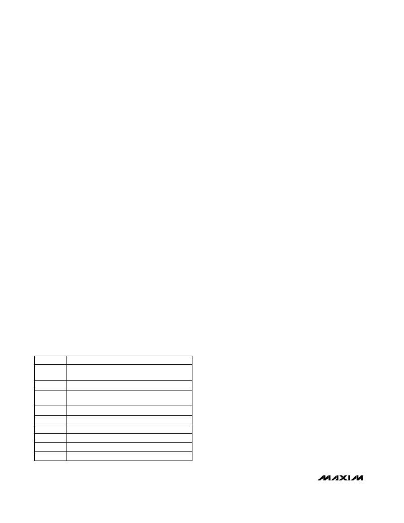
�Table� 1.� Input� and� Output� Status� in�
�Battery-Backup� Mode�
�__________Applications� Information�
�These� μP� supervisory� circuits� are� not� short-circuit�
�protected.� Shorting� V� OUT� to� ground—excluding� power-�
�up� transients� such� as� charging� a� decoupling�
�capacitor—destroys� the� device.� Decouple� both� V� CC�
�and� VBATT� pins� to� ground� by� placing� 0.1μF� capacitors�
�as� close� to� the� device� as� possible.�
�Using� a� SuperCap�
�as� a� Backup� Power� Source�
�SuperCaps� ?� are� capacitors� with� extremely� high�
�capacitance� values� (e.g.,� order� of� 0.47F)� for� their� size.�
�Figure� 3� shows� two� ways� to� use� a� SuperCap� as� a�
�backup� power� source.� The� SuperCap� may� be�
�connected� through� a� diode� to� the� 3V� input� (Figure� 3a)�
�or,� if� a� 5V� supply� is� also� available,� the� SuperCap� may�
�be� charged� up� to� the� 5V� supply� (Figure� 3b)� allowing� a�
�longer� backup� period.� Since� VBATT� can� exceed� V� CC�
�while� V� CC� is� above� the� reset� threshold,� there� are� no�
�special� precautions� when� using� these� μP� supervisors�
�with� a� SuperCap.�
�Operation� without� a� Backup�
�Power� Source�
�These� μP� supervisors� were� designed� for� battery-�
�backed� applications.� If� a� backup� battery� is� not� used,�
�connect� both� VBATT� and� V� OUT� to� V� CC� ,� or� use� a�
�different� μP� supervisor� such� as� the� MAX706T/S/R� or�
�MAX708T/S/R.�
�Replacing� the� Backup� Battery�
�The� backup� power� source� can� be� removed� while� V� CC�
�remains� valid,� if� VBATT� is� decoupled� with� a� 0.1μF�
�capacitor� to� ground,� without� danger� of� triggering�
�RESET/� R� E� S� E� T� .� As� long� as� V� CC� stays� above� V� SW� ,�
�battery-backup� mode� cannot� be� entered.�
�Adding� Hysteresis�
�–� —� —� –�
�PIN� NAME�
�V� OUT�
�V� CC�
�PFI�
�–� —� —� –�
�P� F� O�
�WDI�
�–� —� –�
�M� R�
�–� —� —� —� —� –�
�R� E� S� E� T�
�RESET�
�VBATT�
�STATUS�
�Connected� to� VBATT� through� an� internal�
�140� Ω� switch�
�Disconnected� from� V� OUT�
�The� power-fail� comparator� is� disabled� when�
�V� CC� <� V� SW�
�Logic� low� when� V� CC� <� V� SW� or� PFI� <� V� PFT�
�The� watchdog� timer� is� disabled�
�Disabled�
�Low� logic�
�High� impedance�
�Connected� to� V� OUT�
�to� the� Power-Fail� Comparator�
�The� power-fail� comparator� has� a� typical� input�
�hysteresis� of� 10mV.� This� is� sufficient� for� most� applica-�
�tions� where� a� power-supply� line� is� being� monitored�
�through� an� external� voltage� divider� (see� the� Monitoring�
�an� Additional� Power� Supply� section).�
�If� additional� noise� margin� is� desired,� connect� a� resistor�
�between� P� F� O� and� PFI� as� shown� in� Figure� 4a.� Select�
�the� ratio� of� R1� and� R2� such� that� PFI� sees� 1.237V� (V� PFT� )�
�when� V� IN� falls� to� its� trip� point� (V� TRIP� ).� R3� adds� the�
�hysteresis� and� will� typically� be� more� than� 10� times� the�
�value� of� R1� or� R2.� The� hysteresis� window� extends� both�
�above� (V� H� )� and� below� (V� L� )� the� original� trip� point� (V� TRIP� ).�
�SuperCap� is� a� trademark� of� Baknor� Industries.�
�8�
�_______________________________________________________________________________________�
�相关PDF资料 |
PDF描述 |
|---|---|
| RCM18DTMT-S273 | CONN EDGECARD 36POS R/A .156 SLD |
| ECC50DREN-S13 | CONN EDGECARD 100POS .100 EXTEND |
| ACC08DRTN-S13 | CONN EDGECARD 16POS .100 EXTEND |
| ECC50DREH-S13 | CONN EDGECARD 100POS .100 EXTEND |
| SCEP134S-6R4 | INDUCTOR SMD 6.40UH 8.00A 100KHZ |
相关代理商/技术参数 |
参数描述 |
|---|---|
| MAX802SCSA+ | 功能描述:监控电路 3/3.3V MPU Supervisor RoHS:否 制造商:STMicroelectronics 监测电压数: 监测电压: 欠电压阈值: 过电压阈值: 输出类型:Active Low, Open Drain 人工复位:Resettable 监视器:No Watchdog 电池备用开关:No Backup 上电复位延迟(典型值):10 s 电源电压-最大:5.5 V 最大工作温度:+ 85 C 安装风格:SMD/SMT 封装 / 箱体:UDFN-6 封装:Reel |
| MAX802SCSA+T | 功能描述:监控电路 3/3.3V MPU Supervisor RoHS:否 制造商:STMicroelectronics 监测电压数: 监测电压: 欠电压阈值: 过电压阈值: 输出类型:Active Low, Open Drain 人工复位:Resettable 监视器:No Watchdog 电池备用开关:No Backup 上电复位延迟(典型值):10 s 电源电压-最大:5.5 V 最大工作温度:+ 85 C 安装风格:SMD/SMT 封装 / 箱体:UDFN-6 封装:Reel |
| MAX802SCSA-T | 功能描述:监控电路 RoHS:否 制造商:STMicroelectronics 监测电压数: 监测电压: 欠电压阈值: 过电压阈值: 输出类型:Active Low, Open Drain 人工复位:Resettable 监视器:No Watchdog 电池备用开关:No Backup 上电复位延迟(典型值):10 s 电源电压-最大:5.5 V 最大工作温度:+ 85 C 安装风格:SMD/SMT 封装 / 箱体:UDFN-6 封装:Reel |
| MAX802SEPA | 功能描述:监控电路 RoHS:否 制造商:STMicroelectronics 监测电压数: 监测电压: 欠电压阈值: 过电压阈值: 输出类型:Active Low, Open Drain 人工复位:Resettable 监视器:No Watchdog 电池备用开关:No Backup 上电复位延迟(典型值):10 s 电源电压-最大:5.5 V 最大工作温度:+ 85 C 安装风格:SMD/SMT 封装 / 箱体:UDFN-6 封装:Reel |
| MAX802SEPA+ | 功能描述:监控电路 RoHS:否 制造商:STMicroelectronics 监测电压数: 监测电压: 欠电压阈值: 过电压阈值: 输出类型:Active Low, Open Drain 人工复位:Resettable 监视器:No Watchdog 电池备用开关:No Backup 上电复位延迟(典型值):10 s 电源电压-最大:5.5 V 最大工作温度:+ 85 C 安装风格:SMD/SMT 封装 / 箱体:UDFN-6 封装:Reel |
发布紧急采购,3分钟左右您将得到回复。