- 您现在的位置:买卖IC网 > PDF目录13336 > MAX808LESA+T (Maxim Integrated Products)IC SUPERVISOR MPU 8-SOIC PDF资料下载
参数资料
| 型号: | MAX808LESA+T |
| 厂商: | Maxim Integrated Products |
| 文件页数: | 10/12页 |
| 文件大小: | 0K |
| 描述: | IC SUPERVISOR MPU 8-SOIC |
| 产品培训模块: | Lead (SnPb) Finish for COTS Obsolescence Mitigation Program |
| 标准包装: | 2,500 |
| 类型: | 备用电池电路 |
| 监视电压数目: | 1 |
| 复位: | 低有效 |
| 复位超时: | 最小为 140 ms |
| 电压 - 阀值: | 4.675V |
| 工作温度: | -40°C ~ 85°C |
| 安装类型: | 表面贴装 |
| 封装/外壳: | 8-SOIC(0.154",3.90mm 宽) |
| 供应商设备封装: | 8-SOIC |
| 包装: | 带卷 (TR) |
�� �
�
�8-Pin� μP� Supervisory� Circuits�
�with� ±1.5%� Reset� Accuracy�
�MAX801� Watchdog� Timer�
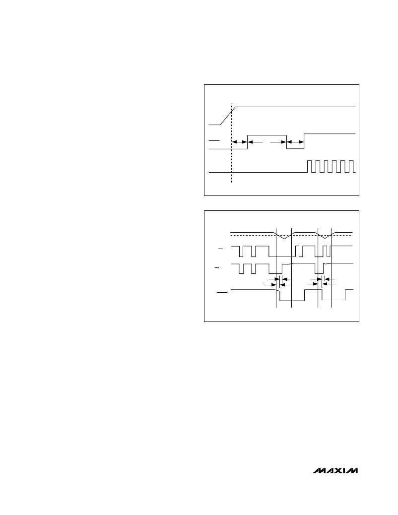
�The� watchdog� monitors� the� μP’s� activity.� If� the� μP� does�
�not� toggle� the� watchdog� input� (WDI)� within� 1.6sec,�
�reset� asserts� for� the� reset� timeout� period.� The� internal�
�1.6sec� timer� is� cleared� when� reset� asserts� or� when� a�
�transition� (low-to-high� or� high-to-low)� occurs� at� WDI�
�while� reset� is� not� asserted.� The� timer� remains� cleared�
�V� CC�
�and� does� not� count� as� long� as� reset� is� asserted.� It�
�starts� counting� as� soon� as� reset� is� released� (Figure� 5).�
�Supply� current� is� typically� reduced� by� 10μA� when� WDI�
�is� at� a� valid� logic� level.� To� disable� the� watchdog� func-�
�tion,� leave� WDI� unconnected.� An� internal� voltage�
�divider� sets� WDI� to� about� mid-supply,� disabling� the�
�watchdog� timer/counter.�
�MAX808� Chip-Enable� Gating�
�RESET�
�WDI�
�t� RP�
�t� WD�
�t� RP�
�The� MAX808� provides� internal� gating� of� chip-enable�
�(CE)� signals� to� prevent� erroneous� data� from� corrupting�
�CMOS� RAM� in� the� event� of� a� power� failure.� During� nor-�
�mal� operation,� the� CE� gate� is� enabled� and� passes� all�
�CE� transitions.� When� reset� is� asserted,� this� path�
�becomes� disabled,� preventing� erroneous� data� from�
�corrupting� the� CMOS� RAM.� The� MAX808� uses� a� series�
�transmission� gate� from� the� chip-enable� input� (� CE� IN)� to�
�the� chip-enable� output� (� CE� OUT)� (Figure� 1).� The� 8ns�
�max� chip-enable� propagation� from� CE� IN� to� CE� OUT�
�enables� the� MAX808� to� be� used� with� most� μPs.�
�Figure� 5.� Watchdog� Timing�
�V� CC�
�RESET�
�THRESHOLD�
�CE� IN�
�CE� OUT�
�The� MAX808� also� features� write-cycle-completion� cir-�
�cuitry.� If� V� CC� falls� below� the� reset� threshold� while� the�
�μP� is� writing� to� RAM,� the� MAX808� holds� the� CE� gate�
�enabled� for� 18μs� to� allow� the� μP� to� complete� the� write�
�instruction.� If� the� write� cycle� has� not� completed� by� the�
�end� of� the� 18μs� period,� the� CE� transmission� gate� turns�
�off� and� CE� OUT� goes� high.� If� the� μP� completes� the�
�RESET�
�18� μ� s�
�17� μ� s�
�18� μ� s�
�17� μ� s�
�write� instruction� during� the� 18μs� period,� the� CE� gate�
�turns� off� (high� impedance)� and� CE� OUT� goes� high� as�
�soon� as� the� μP� pulls� CE� IN� high.� CE� OUT� remains� high,�
�even� if� CE� IN� falls� low� for� any� reason� (Figure� 6).�
�Chip-Enable� Input�
�CE� IN� is� high� impedance� (disabled� mode)� while� reset� is�
�asserted.� During� a� power-down� sequence� when� V� CC�
�passes� the� reset� threshold,� the� CE� transmission� gate�
�disables.� CE� IN� becomes� high� impedance� 18μs� after�
�reset� asserts,� provided� CE� IN� is� still� low.� If� the� μP� com-�
�pletes� the� write� instruction� during� the� 18μs� period,� the�
�CE� gate� turns� off.� CE� IN� becomes� high� impedance� as�
�soon� as� the� μP� pulls� CE� IN� high.� CE� IN� remains� high�
�impedance� even� if� the� signal� at� CE� IN� falls� low� (Figure�
�6).� During� a� power-up� sequence,� CE� IN� remains� high�
�impedance� (regardless� of� CE� IN� activity)� until� reset� is�
�deasserted� following� the� reset� timeout� period.�
�Figure� 6.� Chip-Enable� Timing�
�In� high-impedance� mode,� the� leakage� currents� into� this�
�input� are� ±1μA� max� over� temperature.� In� low-imped-�
�ance� mode,� the� impedance� of� CE� IN� appears� as� a� 75� Ω�
�resistor� in� series� with� the� load� at� CE� OUT.�
�The� propagation� delay� through� the� CE� transmission�
�gate� depends� on� both� the� source� impedance� of� the�
�drive� to� CE� IN� and� the� capacitive� loading� on� CE� OUT�
�(see� the� Chip-Enable� Propagation� Delay� vs.� CE� OUT�
�Load� Capacitance� graph� in� the� Typical� Operating�
�Characteristics� ).� The� CE� propagation� delay� is� produc-�
�tion� tested� from� the� 50%� point� on� CE� IN� to� the� 50%�
�point� on� CE� OUT� using� a� 50� Ω� driver� and� 50pF� of� load�
�capacitance� (Figure� 7).� For� minimum� propagation�
�delay,� minimize� the� capacitive� load� at� CE� OUT� and� use�
�a� low-output-impedance� driver.�
�10�
�______________________________________________________________________________________�
�相关PDF资料 |
PDF描述 |
|---|---|
| SP6201EM5-L-1-5 | IC REG LDO 1.5V .2A SOT23-5 |
| VI-J6J-EY-F2 | CONVERTER MOD DC/DC 36V 50W |
| MAX708REUA+ | IC SUPERVISOR MPU 8-UMAX |
| 400TXW39MEFC10X40 | CAP ALUM 39UF 400V 20% RADIAL |
| CS5171ED8G | IC REG MULTI CONFIG 1.5A 8SOIC |
相关代理商/技术参数 |
参数描述 |
|---|---|
| MAX808LMJA | 功能描述:监控电路 RoHS:否 制造商:STMicroelectronics 监测电压数: 监测电压: 欠电压阈值: 过电压阈值: 输出类型:Active Low, Open Drain 人工复位:Resettable 监视器:No Watchdog 电池备用开关:No Backup 上电复位延迟(典型值):10 s 电源电压-最大:5.5 V 最大工作温度:+ 85 C 安装风格:SMD/SMT 封装 / 箱体:UDFN-6 封装:Reel |
| MAX808M | 制造商:MAXIM 制造商全称:Maxim Integrated Products 功能描述:Dual Universal Switched Capacitor Filter[MF10/MF10BJ/MF10BN/MF10BWP/MF10BWP-T/MF10CC/D/MF10CJ/MF10CN/MF10CWP/MF10CWP-T ] |
| MAX808MCPA | 功能描述:监控电路 RoHS:否 制造商:STMicroelectronics 监测电压数: 监测电压: 欠电压阈值: 过电压阈值: 输出类型:Active Low, Open Drain 人工复位:Resettable 监视器:No Watchdog 电池备用开关:No Backup 上电复位延迟(典型值):10 s 电源电压-最大:5.5 V 最大工作温度:+ 85 C 安装风格:SMD/SMT 封装 / 箱体:UDFN-6 封装:Reel |
| MAX808MCPA+ | 功能描述:监控电路 8-Pin uPower Supervisor RoHS:否 制造商:STMicroelectronics 监测电压数: 监测电压: 欠电压阈值: 过电压阈值: 输出类型:Active Low, Open Drain 人工复位:Resettable 监视器:No Watchdog 电池备用开关:No Backup 上电复位延迟(典型值):10 s 电源电压-最大:5.5 V 最大工作温度:+ 85 C 安装风格:SMD/SMT 封装 / 箱体:UDFN-6 封装:Reel |
| MAX808MCSA | 功能描述:监控电路 RoHS:否 制造商:STMicroelectronics 监测电压数: 监测电压: 欠电压阈值: 过电压阈值: 输出类型:Active Low, Open Drain 人工复位:Resettable 监视器:No Watchdog 电池备用开关:No Backup 上电复位延迟(典型值):10 s 电源电压-最大:5.5 V 最大工作温度:+ 85 C 安装风格:SMD/SMT 封装 / 箱体:UDFN-6 封装:Reel |
发布紧急采购,3分钟左右您将得到回复。