- 您现在的位置:买卖IC网 > PDF目录17222 > MAX8569EVKIT+ (Maxim Integrated Products)EVALUATION KIT FOR MAX8569 PDF资料下载
参数资料
| 型号: | MAX8569EVKIT+ |
| 厂商: | Maxim Integrated Products |
| 文件页数: | 8/11页 |
| 文件大小: | 0K |
| 描述: | EVALUATION KIT FOR MAX8569 |
| 产品培训模块: | Lead (SnPb) Finish for COTS Obsolescence Mitigation Program |
| 标准包装: | 1 |
| 主要目的: | DC/DC,步升 |
| 输出及类型: | 1,非隔离 |
| 电流 - 输出: | 200mA |
| 输入电压: | 1.5 ~ 5.5 V |
| 稳压器拓扑结构: | 升压 |
| 板类型: | 完全填充 |
| 已供物品: | 板 |
| 已用 IC / 零件: | MAX8569 |
�� �
�
�200mA� Step-Up� Converters� in� 6-Pin�
�SOT23� and� TDFN�
�Low-Battery� Cutoff�
�The� SHDN� trip� threshold� of� the� MAX8569A/MAX8569B�
�can� be� used� as� an� input� voltage� detector� that� disables�
�the� IC� when� the� battery� voltage� falls� to� a� set� level.� The�
�SHDN� trip� threshold� is� 1.228V.� Use� a� resistor-divider� to�
�set� the� battery-detection� voltage� (R1� and� R2� in� Figure� 1).�
�Select� R2� between� 100k� ?� and� 1M� ?� to� minimize� battery�
�drain.� Calculate� R1� as� follows:�
�R1� =� R2� x� ((V� OFF� /� V� SHDN� )� -� 1)�
�where� V� OFF� is� the� battery� voltage� at� which� the� part�
�shuts� down� and� V� SHDN� =� 1.228V.� Note� that� input� ripple�
�can� sometimes� cause� false� shutdowns.� To� minimize� the�
�effect� of� ripple,� connect� a� low-value� capacitor� (C2)�
�from� SHDN� to� GND� to� filter� out� input� noise.� Select� a� C2�
�value� so� the� R1,� C2� time� constant� is� above� 2ms.�
�Power-On� Reset� (� RST,� MAX8569B)�
�The� MAX8569B� provides� a� power-on� reset� output� (� RST� )�
�that� goes� high� impedance� when� the� output� reaches� 90%�
�of� its� regulation� point.� RST� pulls� low� when� the� output� is�
�below� 90%� of� the� regulation� point.� Connect� a� 100k� ?� to�
�1M� ?� pullup� resistor� from� RST� to� OUT� to� provide� a� logic�
�control� signal� for� a� microprocessor.� Connect� RST� to�
�GND� when� the� reset� function� is� not� used.�
�Setting� the� Output� Voltage� (MAX8569A)�
�The� output� of� the� MAX8569A� is� adjustable� from� 2V� to�
�5.5V.� Connect� a� resistor-divider� from� the� output� to� ground�
�with� FB� connected� to� the� center� tap� to� set� the� desired�
�output� voltage� (R3� and� R4,� Figure� 1).� Select� R4� between�
�100k� ?� and� 1M� ?� .� R3� is� then� calculated� as� follows:�
�R3� =� R4� x� ((V� OUT� /� V� FB� )� -� 1)�
�where� V� OUT� is� the� desired� output� voltage� and� V� FB� is�
�1.228V.�
�where� R� L� is� the� inductor� series� resistance� and� R� NCH� is�
�the� R� DS(ON)� of� the� internal� n-channel� MOSFET� (0.3� ?� typ).�
�Capacitor� Selection�
�Choose� an� output� capacitor� to� achieve� the� desired� out-�
�put� ripple� percentage.�
�C� OUT� >� (0.5� x� L� x� 0.780A� 2� )� /� (r%� x� V� OUT� 2� )�
�where� L� is� the� inductor� value� and� r� is� the� desired� output�
�ripple� in� %.� A� 22μF� ceramic� capacitor� is� a� good� start-�
�ing� value.�
�The� input� capacitor� reduces� the� peak� current� drawn�
�from� the� battery� and� can� be� the� same� value� as� the� out-�
�put� capacitor.� A� larger� input� capacitor� can� be� used� to�
�further� reduce� the� input� ripple� and� improve� efficiency.�
�PC� Board� Layout� and� Grounding�
�Careful� printed� circuit� layout� is� important� for� minimizing�
�ground� bounce� and� noise.� Keep� the� IC� ’� s� GND� pin� and�
�the� ground� leads� of� the� input-� and� output-filter� capaci-�
�tors� less� than� 0.2in� (5mm)� apart.� In� addition,� keep� all�
�connections� to� the� FB� and� LX� pins� as� short� as� possible.�
�In� particular,� when� using� external� feedback� resistors,�
�locate� them� as� close� to� FB� as� possible.� To� maximize�
�output� power� and� efficiency� and� minimize� output� ripple�
�voltage,� use� a� ground� plane� and� solder� the� IC� ’� s� GND�
�directly� to� the� ground� plane.� A� sample� layout� is� avail-�
�able� in� the� MAX8569A/MAX8569B� evaluation� kit� to�
�speed� designs.�
�Chip� Information�
�PROCESS:� BiCMOS�
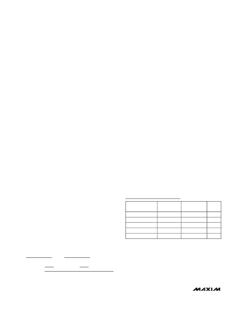
�Selector� Guide�
�Inductor� Selection�
�The� control� scheme� of� the� MAX8569A/MAX8569B� per-�
�mits� flexibility� in� choosing� an� inductor.� A� 10μH� inductor�
�performs� well� for� most� applications,� but� values� from�
�4.7μH� to� 100μH� can� be� used� as� well.� Small� inductance�
�values� typically� offer� smaller� physical� size.� Output�
�power� is� reduced� when� the� inductance� is� large� enough�
�to� prevent� the� maximum� current� limit� (780mA)� from�
�PART�
�MAX8569AEUT�
�MAX8569BEUT�
�MAX8569AETT�
�MAX8569BETT�
�MAX8569BETT30�
�OUTPUT�
�VOLTAGE�
�Adjustable�
�Fixed� 3.3V�
�Adjustable�
�Fixed� 3.3V�
�Fixed� 3.0V�
�PIN-�
�PACKAGE�
�SOT23-6�
�SOT23-6�
�TDFN�
�TDFN�
�TDFN�
�TOP�
�MARK�
�ABWK�
�ABWL�
�AJN�
�AJO�
�AJP�
�being� reached� before� the� maximum� on-time� (5μs)�
�expires.� For� maximum� output� current,� choose� L� so� that:�
�V� BATT� (� MAX� )� ×� 1� μ� s�
�0� .� 78� A�
�<� L� <�
�V� BATT� (� MIN� )� ×� 5� μ� s�
�0� .� 78� A�
�� ?� V� BATT� (� MIN� )� ?� � (� R� NCH� +� R� L� )� ?�
�I� OUT� (� MAX� )� =�
�0� .� 78� A�
�2�
�?� 0� .� 78� A� ?�
�?� 2� ?�
�V� OUT�
�8�
�_______________________________________________________________________________________�
�相关PDF资料 |
PDF描述 |
|---|---|
| CURMT101-HF | DIODE FAST 50V 1A SOD-123H |
| IRS21844SPBF | IC DRIVER HALF-BRIDGE 14-SOIC |
| CFRMT105-HF | DIODE FAST 600V 1A SOD-123H |
| MAX15034BEVKIT+ | KIT EVALUATION FOR MAX15034 |
| ESM06DSXS | CONN EDGECARD 12POS DIP .156 SLD |
相关代理商/技术参数 |
参数描述 |
|---|---|
| MAX8569EVKIT+ | 功能描述:电源管理IC开发工具 MAX8569 Eval Kit RoHS:否 制造商:Maxim Integrated 产品:Evaluation Kits 类型:Battery Management 工具用于评估:MAX17710GB 输入电压: 输出电压:1.8 V |
| MAX856C/D | 功能描述:直流/直流开关转换器 DICE SALES DICE RoHS:否 制造商:STMicroelectronics 最大输入电压:4.5 V 开关频率:1.5 MHz 输出电压:4.6 V 输出电流:250 mA 输出端数量:2 最大工作温度:+ 85 C 安装风格:SMD/SMT |
| MAX856C/D DIE | 制造商:Maxim Integrated Products 功能描述: |
| MAX856CPA | 功能描述:直流/直流开关转换器 RoHS:否 制造商:STMicroelectronics 最大输入电压:4.5 V 开关频率:1.5 MHz 输出电压:4.6 V 输出电流:250 mA 输出端数量:2 最大工作温度:+ 85 C 安装风格:SMD/SMT |
| MAX856CSA | 功能描述:直流/直流开关转换器 3.3/5/AdjV Step-Up DC/DC Converter RoHS:否 制造商:STMicroelectronics 最大输入电压:4.5 V 开关频率:1.5 MHz 输出电压:4.6 V 输出电流:250 mA 输出端数量:2 最大工作温度:+ 85 C 安装风格:SMD/SMT |
发布紧急采购,3分钟左右您将得到回复。