- 您现在的位置:买卖IC网 > PDF目录5151 > MAX8575EUT+T (Maxim Integrated Products)IC CONV LCD BOOST SOT23-6 PDF资料下载
参数资料
| 型号: | MAX8575EUT+T |
| 厂商: | Maxim Integrated Products |
| 文件页数: | 8/11页 |
| 文件大小: | 0K |
| 描述: | IC CONV LCD BOOST SOT23-6 |
| 产品培训模块: | Lead (SnPb) Finish for COTS Obsolescence Mitigation Program |
| 标准包装: | 2,500 |
| 应用: | 转换器,LCD |
| 输入电压: | 2.7 V ~ 5.5 V |
| 输出数: | 1 |
| 输出电压: | 15V |
| 工作温度: | -40°C ~ 85°C |
| 安装类型: | 表面贴装 |
| 封装/外壳: | SOT-23-6 |
| 供应商设备封装: | SOT-6 |
| 包装: | 带卷 (TR) |
�� �
�
�High-Efficiency� LCD� Boost�
�with� True� Shutdown�
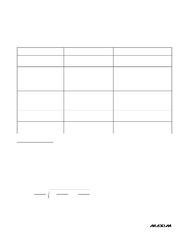
�Table� 1.� Protection� Features�
�COMMON� APPLICATION� FAULTS�
�OUT� to� FB� resistor� missing� or�
�disconnected.�
�Output� cap� missing� and� FB� open.�
�FB� shorted� to� GND.�
�Diode� missing� or� disconnected.�
�Diode� reverse� polarity.�
�FB� node� open.�
�OUT� shorted� to� ground.�
�RESULT� WITH� COMPETING�
�STEP-UP� CONVERTERS�
�OUT� voltage� rises� until� the� output�
�capacitor� is� destroyed� and/or�
�downstream� components� are� damaged.�
�OUT� voltage� rises� until� the� output�
�capacitor� is� destroyed� and/or�
�downstream� components� are� damaged.�
�OUT� voltage� rises� until� the� output�
�capacitor� is� destroyed� and/or�
�downstream� components� are� damaged.�
�Inductor� energy� forces� LX� node� high,�
�possibly� damaging� the� internal� switch.�
�Unpredictable,� possibly� boosting� output�
�voltage� beyond� acceptable� design�
�range.�
�Current� ramps� up� through� inductor� and�
�diode,� generally� destroying� one� of� the�
�RESULT� WITH� MAX8570� FAMILY�
�Converter� stops� switching.�
�LX� may� boost� one� or� two� times� before� the� FB�
�voltage� exceeds� the� trip� point.� In� the� rare� case�
�where� the� capacitive� loading� and� external�
�loading� on� OUT� is� small� enough� that� the� energy�
�in� one� cycle� can� slew� it� more� than� 50V,� the�
�internal� MOSFET� will� clamp� between� 35V� and�
�70V� (nondestructively).�
�Converter� stops� switching� and� OUT� is� resistively�
�loaded� to� GND.�
�OUT� is� resistively� loaded� to� GND� and� the�
�converter� stops� switching.�
�FB� node� driven� above� its� regulation� point,� the�
�converter� stops� switching,� and� OUT� is� resistively�
�loaded� to� GND.�
�True� off-switch� detects� short,� opens� when�
�current� reaches� pMOS� current� limit,� and� restarts�
�devices.�
�Design� Procedure�
�Inductor� Selection�
�Smaller� inductance� values� typically� offer� smaller� physi-�
�cal� size� for� a� given� series� resistance� or� saturation� cur-�
�rent.� Circuits� using� larger� inductance� values� may�
�provide� more� output� power.� The� inductor’s� saturation�
�current� rating� should� be� greater� than� the� peak� switch-�
�ing� current.� Recommended� inductor� values� range� from�
�10μH� to� 100μH.�
�Selecting� the� Current� Limit�
�The� peak� LX� current� limit� (I� LX(MAX)� )� required� for� the�
�application� is� calculated� from� the� following� equation:�
�soft-start.� This� protects� the� inductor� and� diode.�
�value.� See� the� Selector� Guide� on� page� 1� for� selecting�
�the� IC� with� the� correct� current� limit.�
�Diode� Selection�
�The� high� switching� frequency� of� up� to� 800kHz� requires�
�a� high-speed� rectifier.� Schottky� diodes� are� recom-�
�mended� due� to� their� low� forward-voltage� drop.� To�
�maintain� high� efficiency,� the� average� current� rating� of�
�the� diode� should� be� greater� than� the� peak� switching�
�current.� Choose� a� reverse� breakdown� voltage� greater�
�than� the� output� voltage.�
�Capacitors�
�Small� ceramic� surface-mount� capacitors� with� X7R� or�
�X5R� temperature� characteristics� are� recommended�
�due� to� their� small� size,� low� cost,� low� equivalent� series�
�P� OUT� (� MAX� )� ?�
�I� LX� (� MAX� )� ≥� 1� .� 25� ×�
�P� OUT� (� MAX� )�
�V� BATT� (� MIN� )�
�?�
�+� ?� 1� .� 25� �
�?�
�2�
�?� +� 3� μ� s� ×�
�V� BATT� (� MIN� )� ?�
�P� OUT� (� MAX� )�
�L�
�resistance� (ESR),� and� low� equivalent� series� inductance�
�(ESL).� If� nonceramic� capacitors� are� used,� it� is� important�
�that� they� have� low� ESR� to� reduce� the� output� ripple� volt-�
�age� and� peak-peak� load-transient� voltage.�
�where� P� OUT(MAX)� is� the� maximum� output� power�
�required� by� the� load� and� V� BATT(MIN)� is� the� minimum�
�supply� voltage� used� to� supply� the� inductor� (this� is� V� CC�
�unless� a� separate� supply� is� used� for� the� inductor).� The�
�IC� current� limit� must� be� greater� than� this� calculated�
�For� most� applications,� use� a� 1μF� ceramic� capacitor� for�
�the� output� and� V� CC� bypass� capacitors.� For� SW� or� the�
�inductor� supply,� a� 4.7μF� or� greater� ceramic� capacitor�
�is� recommended.�
�8�
�_______________________________________________________________________________________�
�相关PDF资料 |
PDF描述 |
|---|---|
| ACM18DTKS | CONN EDGECARD 36POS DIP .156 SLD |
| AVS337M06E16B-F | CAP ALUM 330UF 6.3V 20% SMD |
| MAX8574EUT+T | IC CONV LCD BOOST SOT23-6 |
| X40410V8I-AT1 | IC VOLTAGE MON DUAL W/SUP 8TSSOP |
| UA78L05CPKG3 | IC REG LDO 5V .1A SOT89-3 |
相关代理商/技术参数 |
参数描述 |
|---|---|
| MAX8576EUB | 功能描述:DC/DC 开关控制器 RoHS:否 制造商:Texas Instruments 输入电压:6 V to 100 V 开关频率: 输出电压:1.215 V to 80 V 输出电流:3.5 A 输出端数量:1 最大工作温度:+ 125 C 安装风格: 封装 / 箱体:CPAK |
| MAX8576EUB+ | 功能描述:DC/DC 开关控制器 3-28V Hystrtic Synch Step-Down Controller RoHS:否 制造商:Texas Instruments 输入电压:6 V to 100 V 开关频率: 输出电压:1.215 V to 80 V 输出电流:3.5 A 输出端数量:1 最大工作温度:+ 125 C 安装风格: 封装 / 箱体:CPAK |
| MAX8576EUB+T | 功能描述:DC/DC 开关控制器 3-28V Hystrtic Synch Step-Down Controller RoHS:否 制造商:Texas Instruments 输入电压:6 V to 100 V 开关频率: 输出电压:1.215 V to 80 V 输出电流:3.5 A 输出端数量:1 最大工作温度:+ 125 C 安装风格: 封装 / 箱体:CPAK |
| MAX8576EUB-T | 功能描述:DC/DC 开关控制器 RoHS:否 制造商:Texas Instruments 输入电压:6 V to 100 V 开关频率: 输出电压:1.215 V to 80 V 输出电流:3.5 A 输出端数量:1 最大工作温度:+ 125 C 安装风格: 封装 / 箱体:CPAK |
| MAX8576EVKIT | 功能描述:DC/DC 开关控制器 MAX8576 Evaluation Kit RoHS:否 制造商:Texas Instruments 输入电压:6 V to 100 V 开关频率: 输出电压:1.215 V to 80 V 输出电流:3.5 A 输出端数量:1 最大工作温度:+ 125 C 安装风格: 封装 / 箱体:CPAK |
发布紧急采购,3分钟左右您将得到回复。