- 您现在的位置:买卖IC网 > PDF目录22307 > MAX8668ETEV+T (Maxim Integrated)IC REG QD BCK/LINEAR SYNC 16TQFN PDF资料下载
参数资料
| 型号: | MAX8668ETEV+T |
| 厂商: | Maxim Integrated |
| 文件页数: | 14/18页 |
| 文件大小: | 388K |
| 描述: | IC REG QD BCK/LINEAR SYNC 16TQFN |
| 产品培训模块: | Lead (SnPb) Finish for COTS Obsolescence Mitigation Program |
| 标准包装: | 2,500 |
| 拓扑: | 降压(降压)同步(2),线性(LDO)(2) |
| 功能: | 任何功能 |
| 输出数: | 4 |
| 频率 - 开关: | 1.5MHz |
| 电压/电流 - 输出 1: | 0.6 V ~ 3.3 V,600mA |
| 电压/电流 - 输出 2: | 0.6 V ~ 3.3 V,1.2A |
| 电压/电流 - 输出 3: | 3.3V,300mA |
| 带 LED 驱动器: | 无 |
| 带监控器: | 无 |
| 带序列发生器: | 无 |
| 电源电压: | 2.6 V ~ 5.5 V |
| 工作温度: | -40°C ~ 85°C |
| 安装类型: | 表面贴装 |
| 封装/外壳: | 16-WFQFN 裸露焊盘 |
| 供应商设备封装: | 16-TQFN-EP(3x3) |
| 包装: | 带卷 (TR) |
1.5MHz Dual Step-Down DC-DC Converters
with Dual LDOs and Individual Enables
14 ______________________________________________________________________________________
for peak ripple current and load transients. The step-
down converters unique architecture has minimal cur-
rent overshoot during startup and load transients and in
most cases, an inductor capable of 1.3x the maximum
load current is acceptable.
For output voltages above 2V, when light-load efficiency
is important, the minimum recommended inductor is
2.2礖. For optimum voltage-positioning load transients,
choose an inductor with DC series resistance in the
50m&to 150m&range. For higher efficiency at heavy
loads (above 200mA) and minimal load regulation,
keep the inductor resistance as small as possible. For
light-load applications (up to 200mA), higher resistance
is acceptable with very little impact on performance.
Capacitor Selection
Input Capacitors
The input capacitor for the step-down converters (C2 in
Figures 3 and 4) reduces the current peaks drawn from
the battery or input power source and reduces switch-
ing noise in the IC. The impedance of C2 at the switch-
ing frequency should be very low. Surface-mount
ceramic capacitors are a good choice due to their
small size and low ESR. Make sure the capacitor main-
tains its capacitance over temperature and DC bias.
Ceramic capacitors with X5R or X7R temperature char-
acteristics generally perform well. A 10礔 ceramic
capacitor is recommended.
A 4.7礔 ceramic capacitor is recommended for the
LDO input capacitor (C3 in Figure3).
Step-Down Output Capacitors
The step-down output capacitors (C6 and C7 in Figures
3 and 4) are required to keep the output-voltage ripple
small and to ensure regulation loop stability. These
capacitors must have low impedance at the switching
frequency. Surface-mount ceramic capacitors are a
good choice due to their small size and low ESR. Make
sure the capacitor maintains its capacitance over tem-
perature and DC bias. Ceramic capacitors with X5R or
X7R temperature characteristics generally perform well.
The output capacitance can be very low. For most appli-
cations, a 2.2礔 ceramic capacitor is sufficient. For C7 of
the MAX8668, a 2.2礔 (V
OUT2
d1.8V) or a 4.7礔 (V
OUT2
> 1.8V) ceramic capacitor is recommended. For opti-
mum load-transient performance and very low output rip-
ple, the output capacitor value in 礔 should be equal to
or greater than the inductor value in 礖.
Feed-Forward Capacitor
The feed-forward capacitors on the MAX8668 (C4 and
C5 in Figure4) set the feedback loop response, control
the switching frequency, and are critical in obtaining
the best efficiency possible. Small X7R and C0G
ceramic capacitors are recommended.
For OUT1, calculate the value of C4 as follows:
C4 = 1.2 x 10
-5
(s/V) x (V
OUT
/ R1)
For OUT2, calculate the value of C5 and C10 as fol-
lows:
C
ff
= 1.2 x 10
-5
(s/V) x (V
OUT
/ R3)
C
ff
= C5 + (C10 / 2)
(C10 / C5) + 1 = (V
OUT
/ V
FB
), where V
FB
is 0.6V.
Rearranging the formulas:
C10 = 2 x C
ff
x (V
OUT
- V
FB
)/(V
OUT
+ V
FB
)
C5 = C
ff
(C10 / 2)
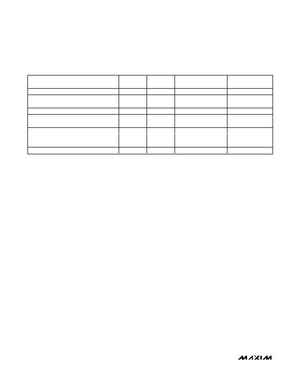
MANUFACTURER
INDUCTOR
L (礖) R
L
(m&) CURRENT RATING (A) L x W x H (mm)
FDK
MIPF2016
2.2
110
1.1
2.0 x 1.6 x 1.0
FDK
MIPF2520D
2.2
80
1.3
2.5 x 2.0 x 1.0
LQH32CN2R2M5
2.2
97
0.79
3.2 x 2.5 x 1.55
Murata
LQM31P
2.2
220
0.9
3.2 x 1.6 x 0.95
Sumida
CDRH2D09
2.2
120
0.44
3.2 x 3.2 x 1.0
TDK
GLF251812T
2.2
200
0.6
2.5 x 1.8 x 1.35
TOKO
D2812C
2.2
140
0.77
2.8 x 2.8 x 1.2
TOKO
MDT2520-CR
2.2
80
0.7
2.5 x 2.0 x 1.0
TPC Series
2.2
55
1.8
4.0 x 4.0 x 1.1
Wurth
TPC Series
4.7
124
1.35
4.0 x 4.0 x 1.1
Taiyo Yuden
CB2518T
2.2
90
0.51
2.5 x 1.8 x 2.0
Table1. Recommended Inductors
相关PDF资料 |
PDF描述 |
|---|---|
| MAX8668ETEW+T | IC REG QD BCK/LINEAR SYNC 16TQFN |
| MAX8668ETEP+ | IC REG QD BCK/LINEAR SYNC 16TQFN |
| MAX8667ETEJS+ | IC REG QD BCK/LINEAR SYNC 16TQFN |
| MAX8667ETEHR+ | IC REG QD BCK/LINEAR SYNC 16TQFN |
| 1N4942GPHE3/54 | DIODE GPP 1A 200V DO-204AL |
相关代理商/技术参数 |
参数描述 |
|---|---|
| MAX8668ETEW+ | 功能描述:直流/直流开关转换器 1.5MHz Dl Step-Down DC/DC Converter RoHS:否 制造商:STMicroelectronics 最大输入电压:4.5 V 开关频率:1.5 MHz 输出电压:4.6 V 输出电流:250 mA 输出端数量:2 最大工作温度:+ 85 C 安装风格:SMD/SMT |
| MAX8668ETEW+T | 功能描述:直流/直流开关转换器 1.5MHz Dl Step-Down DC/DC Converter RoHS:否 制造商:STMicroelectronics 最大输入电压:4.5 V 开关频率:1.5 MHz 输出电压:4.6 V 输出电流:250 mA 输出端数量:2 最大工作温度:+ 85 C 安装风格:SMD/SMT |
| MAX8668ETEX+ | 功能描述:直流/直流开关转换器 1.5MHz Dl Step-Down DC/DC Converter RoHS:否 制造商:STMicroelectronics 最大输入电压:4.5 V 开关频率:1.5 MHz 输出电压:4.6 V 输出电流:250 mA 输出端数量:2 最大工作温度:+ 85 C 安装风格:SMD/SMT |
| MAX8668ETEX+T | 功能描述:直流/直流开关转换器 1.5MHz Dl Step-Down DC/DC Converter RoHS:否 制造商:STMicroelectronics 最大输入电压:4.5 V 开关频率:1.5 MHz 输出电压:4.6 V 输出电流:250 mA 输出端数量:2 最大工作温度:+ 85 C 安装风格:SMD/SMT |
| MAX8668EVKIT+ | 功能描述:直流/直流开关转换器 MAX8668 Evaluation Kit RoHS:否 制造商:STMicroelectronics 最大输入电压:4.5 V 开关频率:1.5 MHz 输出电压:4.6 V 输出电流:250 mA 输出端数量:2 最大工作温度:+ 85 C 安装风格:SMD/SMT |
发布紧急采购,3分钟左右您将得到回复。