- 您现在的位置:买卖IC网 > PDF目录19306 > MAX8785ETI+T (Maxim Integrated)IC CCFL CTRL 28-TQFN PDF资料下载
参数资料
| 型号: | MAX8785ETI+T |
| 厂商: | Maxim Integrated |
| 文件页数: | 16/19页 |
| 文件大小: | 0K |
| 描述: | IC CCFL CTRL 28-TQFN |
| 产品培训模块: | Lead (SnPb) Finish for COTS Obsolescence Mitigation Program |
| 标准包装: | 2,500 |
| 类型: | CCFL 控制器 |
| 电流 - 电源: | 1.5mA |
| 电源电压: | 4.5 V ~ 28 V |
| 工作温度: | -40°C ~ 85°C |
| 封装/外壳: | 28-WFQFN 裸露焊盘 |
| 供应商设备封装: | 28-TQFN-EP(5x5) |
| 包装: | 带卷 (TR) |
�� �
�
�Full-Bridge� Controller� for�
�Piezoelectric� Transformers�
�Setting� the� Lamp� Current�
�The� MAX8785A� senses� the� lamp� current� flowing� through�
�resistor� R1� (Figure� 1)� connected� between� the� low-voltage�
�terminal� of� the� lamp� and� ground.� The� voltage� across� R1�
�is� fed� to� IFB� and� is� internally� full-wave� rectified.� The�
�MAX8785A� controls� the� desired� lamp� current� by� regulat-�
�ing� the� average� of� the� rectified� IFB� voltage.� To� set� the�
�RMS� lamp� current,� select� R1� as� follows:�
�Assuming� the� normal� lamp� operating� voltage� is� 800V�
�and� the� resistor� voltage� rating� is� 200V,� then� n� =� 5.6.�
�Choose� six� resistors� for� the� VFB� string.�
�Setting� the� Arc� Protection� Threshold�
�If� during� normal� operation,� the� PZT� loses� contact� with�
�the� PC� board,� the� MAX8785A� stops� switching.� This� fea-�
�ture� is� referred� to� as� arc� protection.� During� normal�
�operation� when� the� PZT-to-PC� board� connection� is� bro-�
�R� 1� =�
�π� ×� 800� mV�
�2� 2� � I� LAMP� (� RMS� )�
�ken,� a� very� high� voltage� develops� between� the� termi-�
�nals,� resulting� in� arcing.� The� arcing� is� detected� using� a�
�capacitive� voltage-divider� from� the� PZT� high-voltage�
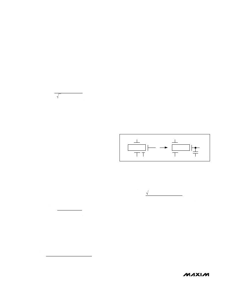
�side� to� the� OLF� pin.� Figure� 7� shows� an� equivalent� high-�
�where� I� LAMP(RMS)� is� the� desired� RMS� lamp� current,�
�and� 800mV� is� the� typical� value� of� the� IFB� regulation�
�point.� To� set� the� RMS� lamp� current� to� 6mA,� the� value� of�
�R1� should� be� 148� Ω� .� The� closest� standard� 1%� resistors�
�are� 147� Ω� and� 150� Ω� .� The� precise� shape� of� the� lamp-�
�current� waveform� depends� on� lamp� parasitics.� The�
�resulting� waveform� is� an� imperfect� sinusoid� waveform,�
�which� has� an� RMS� value� that� is� not� easy� to� predict.� A�
�voltage� capacitor� between� the� bottom� layer� of� the� PZT�
�and� the� metal� layer� of� the� PC� board.� The� lower� layer� of�
�the� PZT� and� metal� layer� of� the� PC� board� creates� a� high-�
�voltage� capacitor.� Terminals� 1� and� 2� are� the� primary�
�side� of� the� PZT,� terminal� 3� is� the� secondary� side,� and�
�terminal� 4� is� the� metal� layer� of� the� PC� board,� which� is�
�the� low-voltage� side� of� the� capacitor� (C� PZT� ).�
�high-frequency� true� RMS� current� meter� (such� as�
�Yokogawa� 2016)� should� be� used� to� measure� the� RMS�
�1�
�1�
�current� and� make� final� adjustments� to� R1.� Insert� this�
�meter� between� the� sense� resistor� and� the� lamp’s� low-�
�T1�
�3�
�T1�
�3�
�voltage� terminal� to� measure� the� actual� RMS� current.�
�PC� BOARD� TRACE�
�Setting� the� Secondary� Voltage� Limit�
�2�
�4�
�2�
�4�
�The� MAX8785A� limits� the� transformer� secondary� volt-�
�age� during� lamp-out� conditions.� The� secondary� voltage�
�is� sensed� through� a� resistive� voltage-divider,� as� shown�
�in� Figure� 1.� The� voltage� at� VFB� is� proportional� to� the�
�CCFL� voltage.� The� total� resistance� from� the� HV� side� to�
�ground� should� be� greater� than� 1M� Ω� so� that� the� resis-�
�tive� voltage-divider� does� not� affect� normal� lamp� opera-�
�Figure� 7.� Arc� Protection�
�C� PZT� and� C1� in� Figure� 1� form� a� capacitive� voltage-�
�divider� to� OLF� pin.� These� capacitors� set� the� maximum�
�secondary� voltage� for� an� ARC� fault.� C1� can� be� calculat-�
�ed� from� the� following� equation:�
�tion.� Resistors� R2� and� R3� through� R9� set� the� maximum�
�secondary� voltage� limit.� The� resistance� of� R2� can� be�
�calculated� as� follows� :�
�C� 1� =�
�2� � V� LAMP� (� RMS� )_� MAX�
�1� .� 2� V�
�� C� PZT�
�R� 2� =�
�V� FB _ OV� � R� VFB�
�V� LAMP� _� MAX�
�C� PZT� should� be� measured� on� the� board.� Refer� to� the�
�MAX8785A� EV� Kit� data� sheet� for� suggested� layout.�
�COMP� Capacitor� Selection�
�where� R� VFB� =� R3� +� R4� +� R5� +� R6� +� R7� +� R8� +� R9� =�
�1.4M� Ω� and� VFB_OV� is� the� overvoltage� threshold.� To� set�
�the� maximum� lamp� voltage� to� 2000V� with� R� VFB� =�
�1.4M� Ω� ,� R2� must� be� equal� to� 1.54k� Ω� .� The� voltage� across�
�each� resistor� during� normal� operation� should� not�
�exceed� its� voltage� rating;� hence,� the� number� of� resistors�
�in� R� VFB� can� be� calculated� from� the� following� equation:�
�COMP� is� the� output� of� the� transconductance� error�
�amplifier� for� the� lamp-current� control� loop.� Connect� a�
�capacitor� between� COMP� and� GND� to� stabilize� the� cur-�
�rent-control� loop.� The� value� of� COMP� capacitance�
�determines� the� response� time� of� the� lamp-current� con-�
�trol� loop.� The� COMP� capacitance� also� determines� the�
�power-on� startup� timing.� The� recommended� COMP�
�n� =�
�LampOperatingVoltage� � 1.4�
�V� SEC� _� MAX�
�capacitance� is� 47nF.�
�16�
�______________________________________________________________________________________�
�相关PDF资料 |
PDF描述 |
|---|---|
| BLP55-1024G | PWR SUPPLY 55W 24V OUT SINGLE |
| TAP476M020BRW | CAP TANT 47UF 20V 20% RADIAL |
| HBC60DREI | CONN EDGECARD 120POS .100 EYELET |
| ECC17DCST | CONN EDGECARD 34POS DIP .100 SLD |
| VE-24K-CW-F1 | CONVERTER MOD DC/DC 40V 100W |
相关代理商/技术参数 |
参数描述 |
|---|---|
| MAX8785EVKIT | 功能描述:显示开发工具 MAX8785 Eval Kit RoHS:否 制造商:4D Systems 产品:4Display Shields 工具用于评估:?OLED-160-G1, ?OLED-160-G2 接口类型:Serial 工作电源电压:5 V |
| MAX8786GTL+ | 制造商:Maxim Integrated Products 功能描述:CONVERTOR - Bulk 制造商:Rochester Electronics LLC 功能描述: |
| MAX878LCSA | 制造商:Maxim Integrated Products 功能描述: |
| MAX878LESA | 制造商:Maxim Integrated Products 功能描述: |
| MAX8790AETP+ | 功能描述:LED照明驱动器 Six-String White LED Driver RoHS:否 制造商:STMicroelectronics 输入电压:11.5 V to 23 V 工作频率: 最大电源电流:1.7 mA 输出电流: 最大工作温度: 安装风格:SMD/SMT 封装 / 箱体:SO-16N |
发布紧急采购,3分钟左右您将得到回复。