- 您现在的位置:买卖IC网 > PDF目录17055 > MAX890LESA+ (Maxim Integrated Products)IC SW MOSFET PUR PCH HSIDE 8SOIC PDF资料下载
参数资料
| 型号: | MAX890LESA+ |
| 厂商: | Maxim Integrated Products |
| 文件页数: | 5/8页 |
| 文件大小: | 0K |
| 描述: | IC SW MOSFET PUR PCH HSIDE 8SOIC |
| 产品培训模块: | Lead (SnPb) Finish for COTS Obsolescence Mitigation Program |
| 标准包装: | 100 |
| 类型: | 高端开关 |
| 输出数: | 1 |
| Rds(开): | 130 毫欧 |
| 内部开关: | 是 |
| 电流限制: | 1.2A |
| 输入电压: | 2.7 V ~ 5.5 V |
| 工作温度: | -40°C ~ 85°C |
| 安装类型: | 表面贴装 |
| 封装/外壳: | 8-SOIC(0.154",3.90mm 宽) |
| 供应商设备封装: | 8-SOIC |
| 包装: | 管件 |
| 产品目录页面: | 1409 (CN2011-ZH PDF) |
�� �
�
�High-Frequency,� Regulated,�
�200mA,� Inverting� Charge� Pump�
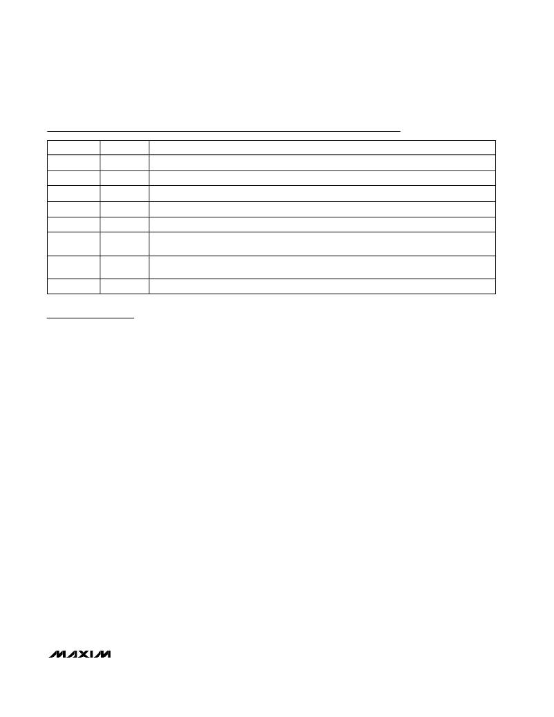
�Pin� Description�
�PIN�
�1�
�2�
�3�
�4�
�5�
�6�
�7�
�8�
�NAME�
�IN�
�CAP+�
�GND�
�CAP-�
�OUT�
�SHDN�
�FB�
�AGND�
�FUNCTION�
�Power-Supply� Positive� Voltage� Input�
�Positive� Terminal� of� Flying� Capacitor�
�Power� Ground�
�Negative� Terminal� of� Flying� Capacitor�
�Inverting� Charge-Pump� Output�
�Shutdown� Control� Input.� Drive� SHDN� low� to� shut� down� the� MAX889.� Connect� SHDN� to� IN� for�
�normal� operation.�
�Feedback� Input.� Connect� FB� to� a� resistor-divider� from� IN� (or� other� positive� reference� voltage�
�source)� to� OUT� for� regulated� output� voltages.� Connect� to� IN� for� free-run� mode.�
�Analog� Ground�
�Detailed� Description�
�The� MAX889� high-current� regulated� charge-pump� DC-�
�DC� inverter� provides� up� to� 200mA.� It� features� the� high-�
�est� available� output� current� while� using� small�
�capacitors� (Table� 1).� The� three� versions� available� differ�
�in� their� switching� frequencies� (f� OSC� )� —� MAX889R/�
�MAX889S/MAX889T� with� f� OSC� =� 500kHz/1MHz/2MHz,�
�respectively.� Higher� frequencies� allow� the� use� of� small-�
�er� components� (Table� 1).� Even� smaller� capacitor� values�
�than� those� listed� in� Table� 1� are� suitable� when� the�
�devices� are� loaded� at� less� than� their� rated� output� cur-�
�rent.� Designed� specifically� for� compact� applications,� a�
�complete� regulating� circuit� requires� only� three� small�
�capacitors� and� two� resistors,� Figure� 1.� In� addition,� the�
�MAX889� includes� soft-start,� shutdown� control,� short-cir-�
�cuit,� and� thermal� protection.�
�The� oscillator,� control� circuitry,� and� four� power� MOSFET�
�switches� are� included� on-chip.� The� charge� pump� runs�
�continuously� at� the� operating� frequency.� During� one-half�
�of� the� oscillator� period,� switches� S1� and� S2� close�
�(Figure� 2),� charging� the� transfer� capacitor� (C� FLY� )� to� the�
�input� voltage� (CAP-� =� GND,� CAP+� =� IN).� During� the�
�other� half� cycle,� switches� S3� and� S4� close� (Figure� 3),�
�transferring� the� charge� on� C� FLY� to� the� output� capacitor�
�(CAP+� =� GND,� CAP-� =� OUT).�
�Voltage� Regulation�
�Voltage� regulation� is� achieved� by� controlling� the� flying-�
�capacitor� charging� rate.� The� MAX889� controls� the�
�charge� on� C� FLY� by� modulating� the� gate� drive� to� S1�
�(Figure� 2)� to� supply� the� charge� necessary� to� maintain�
�output� regulation.� When� the� output� voltage� droops,�
�C� FLY� charges� higher� due� to� increased� gate� drive.� Since�
�the� device� switches� continuously,� the� regulation�
�scheme� minimizes� output� ripple,� and� the� output� noise�
�spectrum� contains� well-defined� frequency� components.�
�Feedback� voltage� is� sensed� with� a� resistor-divider�
�between� an� externally� supplied� positive� reference� or�
�the� supply� voltage� and� the� negative� inverted� output.�
�The� feedback� loop� servos� FB� to� GND.� The� effective�
�output� impedance� in� regulation� is� 0.05� ?� .� The� output�
�remains� in� regulation� until� dropout� is� reached.� Dropout�
�depends� on� the� output� voltage� setting� and� load� current�
�(see� Output� Voltage� vs.� Load� Current� in� Typical�
�Operating� Characteristics� ).�
�Free-Run� Mode�
�(Unregulated� Voltage� Inverter)�
�The� MAX889� may� be� used� in� an� unregulated� voltage�
�inverter� mode� that� does� not� require� external� feedback�
�resistors,� minimizing� board� space.� Connecting� FB� to� IN�
�places� the� MAX889� in� free-run� mode.� In� this� mode,� the�
�charge� pump� operates� to� invert� directly� the� input� sup-�
�ply� voltage� (V� OUT� =� -(V� IN� -� I� OUT� x� R� O� )).� Output� resis-�
�tance� is� typically� 2� ?� and� can� be� approximated� by� the�
�following� equation:�
�R� O� ?� [1� /� (f� OSC� x� C� FLY� )� ]� +� 2R� SW� +�
�4ESR� CFLY� +� ESR� COUT�
�The� first� term� is� the� effective� resistance� of� an� ideal�
�switched-capacitor� circuit� (Figures� 2� and� 3),� and� R� SW�
�is� the� sum� of� the� charge� pump� ’� s� internal� switch� resis-�
�tances� (typically� 0.8� ?� at� V� IN� =� 5V).� The� last� two� terms�
�take� into� consideration� the� equivalent� series� resistance�
�_______________________________________________________________________________________�
�5�
�相关PDF资料 |
PDF描述 |
|---|---|
| GEC31DRAN | CONN EDGECARD 62POS R/A .100 SLD |
| ADR292GRZ-REEL7 | IC VREF SERIES PREC 4.096V 8SOIC |
| ADR291GRZ-REEL7 | IC VREF SERIES PREC 2.5V 8-SOIC |
| 0210391097 | CABLE JUMPER 1MM .030M 39POS |
| AGLN-NANO-KIT | KIT HARDWARE FOR AGLN-NANO |
相关代理商/技术参数 |
参数描述 |
|---|---|
| MAX890LESA/V+ | 功能描述:电源开关 IC - 配电 5/3.3/AdjV 200mA LDO RoHS:否 制造商:Exar 输出端数量:1 开启电阻(最大值):85 mOhms 开启时间(最大值):400 us 关闭时间(最大值):20 us 工作电源电压:3.2 V to 6.5 V 电源电流(最大值): 最大工作温度:+ 85 C 安装风格:SMD/SMT 封装 / 箱体:SOT-23-5 |
| MAX890LESA/V+T | 功能描述:电源开关 IC - 配电 1.2A P-Channel Swtch w/Thermal Shutdown RoHS:否 制造商:Exar 输出端数量:1 开启电阻(最大值):85 mOhms 开启时间(最大值):400 us 关闭时间(最大值):20 us 工作电源电压:3.2 V to 6.5 V 电源电流(最大值): 最大工作温度:+ 85 C 安装风格:SMD/SMT 封装 / 箱体:SOT-23-5 |
| MAX890LESA+ | 功能描述:电源开关 IC - 配电 1.2A Current-Limited High-Side PCh Switch RoHS:否 制造商:Exar 输出端数量:1 开启电阻(最大值):85 mOhms 开启时间(最大值):400 us 关闭时间(最大值):20 us 工作电源电压:3.2 V to 6.5 V 电源电流(最大值): 最大工作温度:+ 85 C 安装风格:SMD/SMT 封装 / 箱体:SOT-23-5 |
| MAX890LESA+T | 功能描述:电源开关 IC - 配电 1.2A Current-Limited High-Side PCh Switch RoHS:否 制造商:Exar 输出端数量:1 开启电阻(最大值):85 mOhms 开启时间(最大值):400 us 关闭时间(最大值):20 us 工作电源电压:3.2 V to 6.5 V 电源电流(最大值): 最大工作温度:+ 85 C 安装风格:SMD/SMT 封装 / 箱体:SOT-23-5 |
| MAX890LESA-T | 功能描述:电源开关 IC - 配电 1.2A Current-Limited High-Side PCh Switch RoHS:否 制造商:Exar 输出端数量:1 开启电阻(最大值):85 mOhms 开启时间(最大值):400 us 关闭时间(最大值):20 us 工作电源电压:3.2 V to 6.5 V 电源电流(最大值): 最大工作温度:+ 85 C 安装风格:SMD/SMT 封装 / 箱体:SOT-23-5 |
发布紧急采购,3分钟左右您将得到回复。