- 您现在的位置:买卖IC网 > PDF目录16966 > MAX894LESA+ (Maxim Integrated Products)IC SW P-CH HS 8-SOIC PDF资料下载
参数资料
| 型号: | MAX894LESA+ |
| 厂商: | Maxim Integrated Products |
| 文件页数: | 7/8页 |
| 文件大小: | 0K |
| 描述: | IC SW P-CH HS 8-SOIC |
| 产品培训模块: | Lead (SnPb) Finish for COTS Obsolescence Mitigation Program |
| 标准包装: | 100 |
| 类型: | 高端开关 |
| 输出数: | 2 |
| Rds(开): | 225 毫欧 |
| 内部开关: | 是 |
| 电流限制: | 500mA |
| 输入电压: | 2.7 V ~ 5.5 V |
| 工作温度: | -40°C ~ 85°C |
| 安装类型: | 表面贴装 |
| 封装/外壳: | 8-SOIC(0.154",3.90mm 宽) |
| 供应商设备封装: | 8-SOIC |
| 包装: | 管件 |
�� �
�
�Dual,� Current-Limited,� High-Side� P-Channel�
�Switches� with� Thermal� Shutdown�
�_______________Detailed� Description�
�The� MAX894L/MAX895L� P-channel� MOSFET� power�
�switches� limit� output� current� to� a� user-programmed�
�level.� When� the� output� current� is� increased� beyond� the�
�SET�
�set� current� level,� the� current� also� increases� through� the�
�replica� switch� (I� OUT� /1050)� (MAX895)� and� through� R� SET�
�(Figure� 1).� The� current-limit� error� amplifier� compares�
�the� voltage� across� R� SET� to� the� internal� 1.24V� reference,�
�and� regulates� the� current� back� to� the� lesser� of� the� pro-�
�MAX894L�
�MAX895L�
�GND�
�R� SET�
�grammed� current� limit� (I� LIMIT� )� or� the� maximum� current�
�limit� (I� MAX� ).�
�These� switches� are� not� bidirectional;� therefore,� the�
�input� voltage� must� be� higher� than� the� output� voltage.�
�Setting� the� Current� Limit�
�The� MAX894L/MAX895L� feature� internal� current-limiting�
�circuitry� with� maximum� programmable� values� (I� MAX� )� of�
�500mA,� and� 250mA,� respectively.� For� best� perfor-�
�mance,� set� the� current� limit� (I� LIMIT� )� between� 0.2I� MAX� ≤�
�I� LIMIT� ≤� I� MAX� .� This� current� limit� remains� in� effect�
�throughout� the� input� supply-voltage� range.�
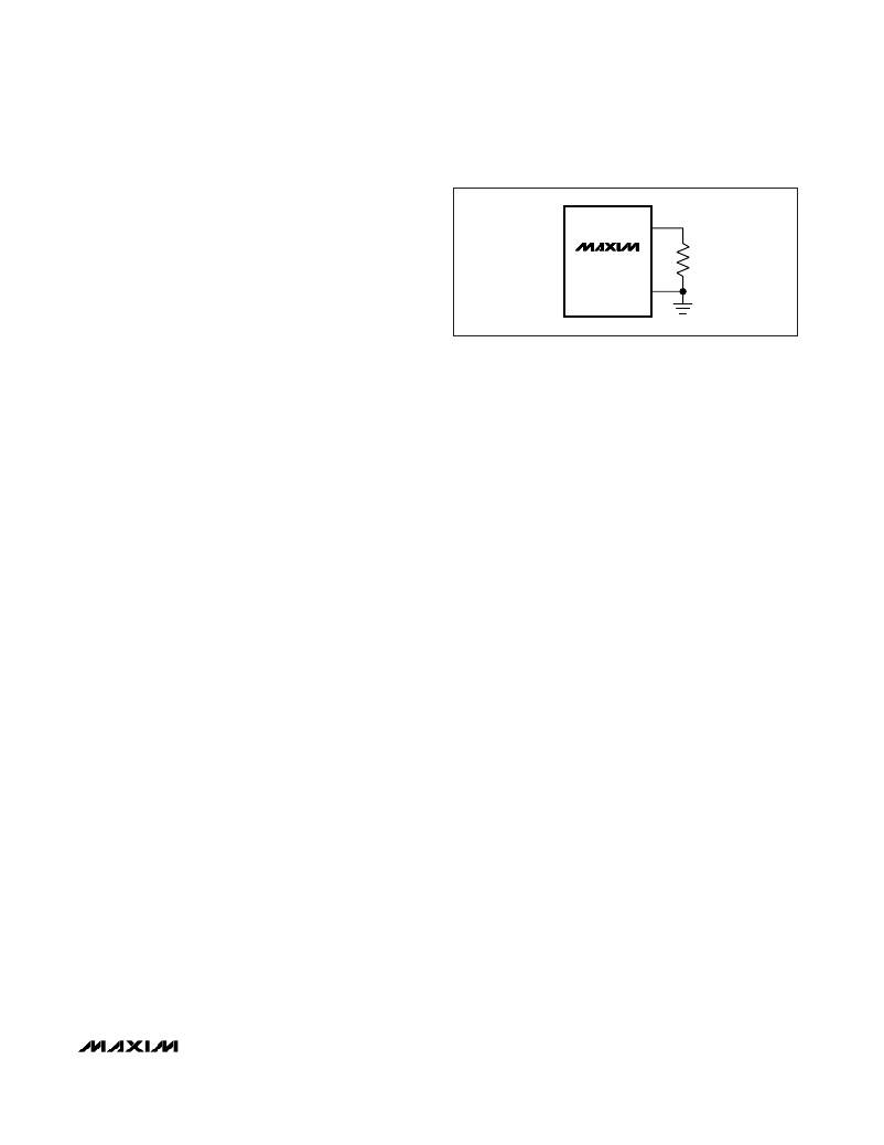
�Program� the� current� limit� with� a� resistor� (R� SET_� )� con-�
�nected� from� SET_� to� ground� (Figure� 2)� as� follows:�
�I� SET� =� I� LIMIT� /� I� RATIO�
�R� SET� =� 1.24V� /� I� SET� =� (1.24V� x� I� RATIO� )� /� I� LIMIT�
�where� I� LIMIT� is� the� desired� current� limit� for� either� switch�
�and� I� RATIO� is� the� I� OUT� to� I� SET� current� ratio� (1085A/A� for�
�the� MAX894L� and� 1050A/A� for� the� MAX895L.�
�Short-Circuit� Protection�
�The� MAX894L/MAX895L� are� short-circuit-protected�
�switches.� In� the� event� of� an� output� short� circuit� or� cur-�
�rent-overload� condition,� the� current� through� either� switch�
�is� limited� by� the� internal� current-limiting� error� amplifier� to�
�1.5� x� I� LIMIT� .� When� the� fault� condition� is� removed,� the�
�replica� error� amplifier� sets� the� current� limit� back� to� I� LIMIT� .�
�For� a� high� ?� V� DS� /� ?� t� during� an� output� short-circuit� condi-�
�tion,� the� switch� turns� off� and� disconnects� the� input� supply�
�from� the� output.� The� current-limiting� amplifier� then� slowly�
�turns� the� switch� on� with� the� output� current� limited� to�
�1.5� x� I� SET� .� When� the� fault� condition� is� removed,� the� current�
�limit� is� set� back� to� I� LIMIT� .� Refer� to� Current-Limit� Response�
�graphs� in� the� Typical� Operating� Characteristics� .�
�Thermal� Shutdown�
�The� MAX894L/MAX895L� feature� thermal� shutdown.� The�
�switch� turns� off� when� the� junction� temperature� exceeds�
�+135°C.� Once� the� device� cools� by� 10°C,� the� switch� turns�
�back� on.� If� the� fault� short-circuit� condition� is� not�
�removed,� the� switch� cycles� on� and� off,� resulting� in� a�
�pulsed� output.�
�Figure� 2.� Setting� the� Current� Limit�
�__________Applications� Information�
�Input� Capacitor�
�To� limit� input� voltage� drop� during� momentary� output�
�short-circuit� conditions,� place� a� capacitor� from� IN� to�
�GND.� A� 1� μ� F� ceramic� capacitor� is� adequate� for� most�
�applications;� however,� higher� capacitor� values� further�
�reduce� voltage� drop� at� the� input.�
�Output� Capacitor�
�Connect� a� 0.1� μ� F� capacitor� from� OUT� to� GND.� This�
�capacitor� prevents� inductive� parasitics� from� pulling�
�OUT� negative� during� turn-off.�
�Layout� and� Thermal-Dissipation�
�Consideration�
�To� take� full� advantage� of� the� switch-response� time� to�
�output� short-circuit� conditions,� it� is� very� important� to�
�keep� all� traces� as� short� as� possible,� reducing� the� effect�
�of� undesirable� parasitic� inductance.� Place� input� and�
�output� capacitors� as� close� as� possible� to� the� device�
�(no� more� than� 5mm).�
�Under� normal� operating� conditions,� the� package� can�
�dissipate� and� channel� heat� away.� Calculate� the� maxi-�
�mum� power� as� follows:�
�P� =� I� 2LIMITA� x� R� ONA� +� I� 2LIMITB� x� R� ONB�
�where� R� ONA� and� R� ONB� are� the� on-resistances� of�
�switches� A� and� B,� respectively.�
�When� one� or� both� outputs� are� short� circuited,� the� volt-�
�age� drop� across� the� switch� equals� the� input� supply.�
�Hence,� the� power� dissipated� across� the� switch� increas-�
�es,� as� does� the� die� temperature.� If� the� fault� condition� is�
�not� removed,� the� thermal-overload-protection� circuitry�
�turns� the� switch� off� until� the� die� temperature� falls� by�
�10°C.� A� ground� plane� in� contact� with� the� device� helps�
�to� further� dissipate� heat.�
�_______________________________________________________________________________________�
�7�
�相关PDF资料 |
PDF描述 |
|---|---|
| 8-1589456-2 | WDUALOBE CONNECTOR |
| KA431SMF2TF | IC VREF SHUNT ADJ SOT-23F |
| 9-1589455-3 | WDUALOBE CONNECTOR |
| SRR0905-390Y | INDUCTOR POWER 39UH 1.1A SMD |
| MAX894LESA+T | IC SW P-CH HS 8-SOIC |
相关代理商/技术参数 |
参数描述 |
|---|---|
| MAX894LESA+ | 功能描述:电源开关 IC - 配电 Current-Limited High-Side PCh Switch RoHS:否 制造商:Exar 输出端数量:1 开启电阻(最大值):85 mOhms 开启时间(最大值):400 us 关闭时间(最大值):20 us 工作电源电压:3.2 V to 6.5 V 电源电流(最大值): 最大工作温度:+ 85 C 安装风格:SMD/SMT 封装 / 箱体:SOT-23-5 |
| MAX894LESA+T | 功能描述:电源开关 IC - 配电 Current-Limited High-Side PCh Switch RoHS:否 制造商:Exar 输出端数量:1 开启电阻(最大值):85 mOhms 开启时间(最大值):400 us 关闭时间(最大值):20 us 工作电源电压:3.2 V to 6.5 V 电源电流(最大值): 最大工作温度:+ 85 C 安装风格:SMD/SMT 封装 / 箱体:SOT-23-5 |
| MAX894LESA-T | 功能描述:电源开关 IC - 配电 Current-Limited High-Side PCh Switch RoHS:否 制造商:Exar 输出端数量:1 开启电阻(最大值):85 mOhms 开启时间(最大值):400 us 关闭时间(最大值):20 us 工作电源电压:3.2 V to 6.5 V 电源电流(最大值): 最大工作温度:+ 85 C 安装风格:SMD/SMT 封装 / 箱体:SOT-23-5 |
| MAX894LESA-TG116 | 制造商:Maxim Integrated Products 功能描述:CURRENT-LIMITED, HIGH-SIDE, P-CHANNEL DUAL SW - Bulk |
| MAX8951EVKIT+ | 制造商:Maxim Integrated Products 功能描述:PWM STEP DOWN CONVERTER - Boxed Product (Development Kits) |
发布紧急采购,3分钟左右您将得到回复。