- 您现在的位置:买卖IC网 > PDF目录10618 > MAX9113EKA+T (Maxim Integrated Products)IC LINE RCVR LVDS DUAL 8SOIC PDF资料下载
参数资料
| 型号: | MAX9113EKA+T |
| 厂商: | Maxim Integrated Products |
| 文件页数: | 9/10页 |
| 文件大小: | 0K |
| 描述: | IC LINE RCVR LVDS DUAL 8SOIC |
| 产品培训模块: | Lead (SnPb) Finish for COTS Obsolescence Mitigation Program |
| 标准包装: | 1 |
| 类型: | 接收器 |
| 驱动器/接收器数: | 0/2 |
| 规程: | LVDS |
| 电源电压: | 3 V ~ 3.6 V |
| 安装类型: | 表面贴装 |
| 封装/外壳: | SOT-23-8 |
| 供应商设备封装: | SOT-23-8 |
| 包装: | 标准包装 |
| 其它名称: | MAX9113EKA+TDKR |
__________ Applications Information
Supply Bypassing
Bypass VCC with high-frequency surface-mount ceram-
ic 0.1F and 0.001F capacitors in parallel, as close to
the device as possible, with the 0.001F valued capaci-
tor the closest to the device. For additional supply
bypassing, place a 10F tantalum or ceramic capacitor
at the point where power enters the circuit board.
Differential Traces
Output trace characteristics affect the performance of
the MAX9111/MAX9113. Use controlled impedance
traces to match trace impedance to both transmission
medium impedance and the termination resistor.
Eliminate reflections and ensure that noise couples as
common mode by running the differential traces close
together. Reduce skew by matching the electrical
length of the traces. Excessive skew can result in a
degradation of magnetic field cancellation.
Maintain the distance between the differential traces to
avoid discontinuities in differential impedance. Avoid
90° turns and minimize the number of vias to further
prevent impedance discontinuities.
Cables and Connectors
Transmission media should have a differential charac-
teristic impedance of about 100
Ω. Use cables and con-
nectors that have matched impedance to minimize
impedance discontinuities.
Avoid the use of unbalanced cables such as ribbon or
simple coaxial cable. Balanced cables such as twisted
pair offer superior signal quality and tend to generate
less EMI due to canceling effects. Balanced cables
tend to pick up noise as common mode, which is
rejected by the LVDS receiver.
Termination
The MAX9111/MAX9113 input differential voltage
depends on the driver current and termination resis-
tance. Refer to the MAX9110/MAX9112 differential dri-
ver data sheet for this information.
Minimize the distance between the termination resistor
and receiver inputs. Use a single 1% to 2% surface-
mount resistor across the receiver inputs.
Board Layout
For LVDS applications, a four-layer PCB that provides
separate power, ground, LVDS signals, and input sig-
nals is recommended. Isolate the input and LVDS sig-
nals from each other to prevent coupling. For best
results, separate the input and LVDS signal planes with
the power and ground planes.
MAX9111/MAX9113
Single/Dual LVDS Line Receivers with
Ultra-Low Pulse Skew in SOT23
8
_______________________________________________________________________________________
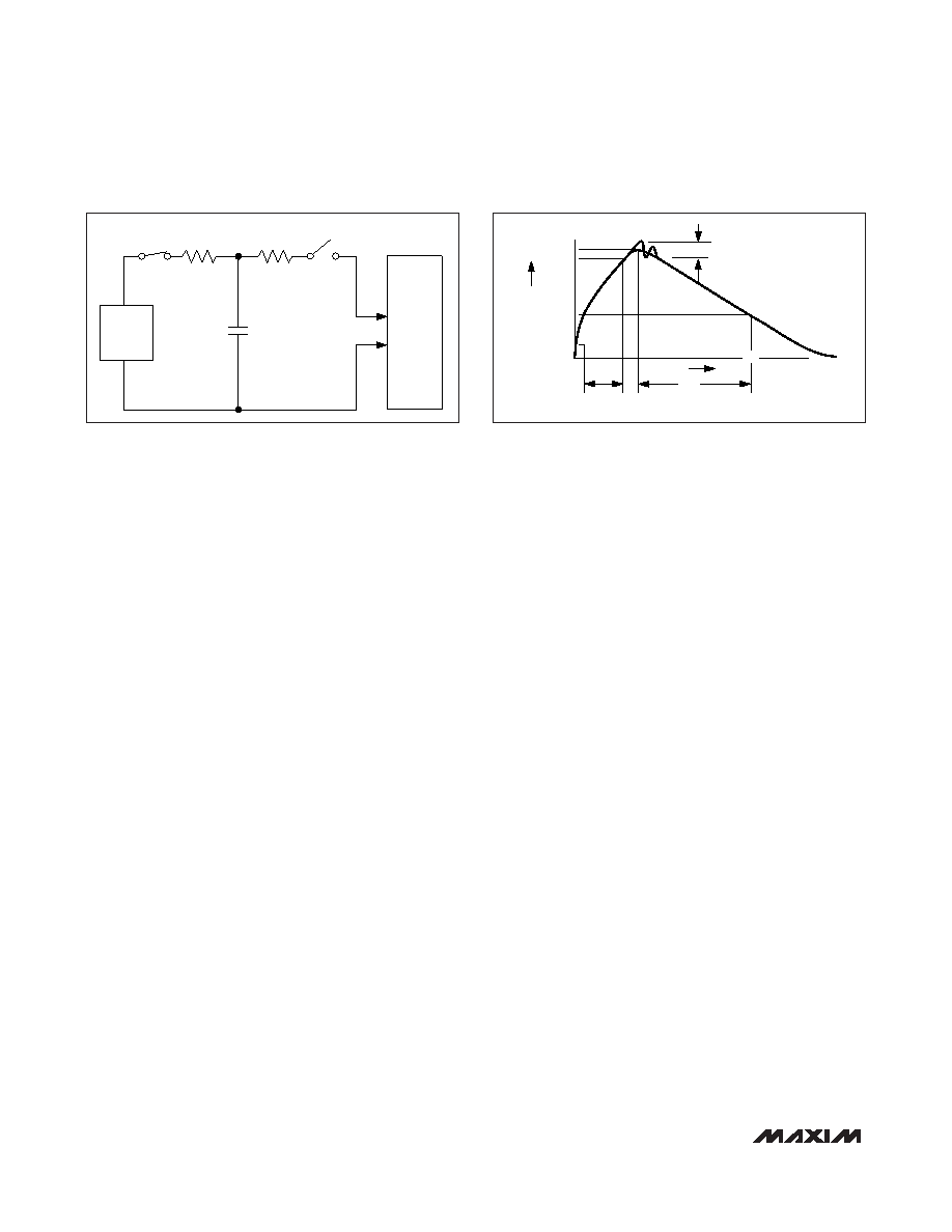
CHARGE-CURRENT
LIMIT RESISTOR
DISCHARGE
RESISTANCE
STORAGE
CAPACITOR
Cs
100pF
RC
1M
Ω
RD
1500
Ω
HIGH-
VOLTAGE
DC
SOURCE
DEVICE
UNDER
TEST
IP 100%
90%
36.8%
tRL
TIME
tDL
CURRENT WAVEFORM
PEAK-TO-PEAK RINGING
(NOT DRAWN TO SCALE)
Ir
10%
0
AMPERES
Figure 3a. Human Body ESD Test Modules
Figure 3b. Human Body Current Waveform
相关PDF资料 |
PDF描述 |
|---|---|
| MAX3209ECUU+ | IC TXRX LP DUAL RS232 38-TSSOP |
| MAX13236EETE+ | TXRX RS-232 250KBPS 1X1 16TQFN |
| MAX3430CSA+ | IC TXRX RS-485 3.3V 8-SOIC |
| SR38-4P-3P | CONN PLUG 3POS MALE SILVER |
| MAX13237EETE+ | TXRX RS-232 3MBPS 1X1 16TQFN |
相关代理商/技术参数 |
参数描述 |
|---|---|
| MAX9113ESA | 制造商:Maxim Integrated Products 功能描述:SINGLE / DUAL LVDS LINE RECEIVER WITH ULTRA-L - Bulk |
| MAX9113ESA+ | 功能描述:LVDS 接口集成电路 Dual-Input Linear Charger RoHS:否 制造商:Texas Instruments 激励器数量:4 接收机数量:4 数据速率:155.5 Mbps 工作电源电压:5 V 最大功率耗散:1025 mW 最大工作温度:+ 85 C 封装 / 箱体:SOIC-16 Narrow 封装:Reel |
| MAX9113ESA+T | 功能描述:LVDS 接口集成电路 Dual-Input Linear Charger RoHS:否 制造商:Texas Instruments 激励器数量:4 接收机数量:4 数据速率:155.5 Mbps 工作电源电压:5 V 最大功率耗散:1025 mW 最大工作温度:+ 85 C 封装 / 箱体:SOIC-16 Narrow 封装:Reel |
| MAX9113ESA-T | 制造商:Maxim Integrated Products 功能描述:SINGLE / DUAL LVDS LINE RECEIVER WITH ULTRA-L - Tape and Reel |
| MAX9115 | 制造商:MAXIM 制造商全称:Maxim Integrated Products 功能描述:Single LVDS Line Receiver in SC70 |
发布紧急采购,3分钟左右您将得到回复。