- 您现在的位置:买卖IC网 > PDF目录1945 > MAX9123EUE+T (Maxim Integrated Products)IC LINE DRVR LVDS QUAD 16TSSOP PDF资料下载
参数资料
| 型号: | MAX9123EUE+T |
| 厂商: | Maxim Integrated Products |
| 文件页数: | 4/10页 |
| 文件大小: | 0K |
| 描述: | IC LINE DRVR LVDS QUAD 16TSSOP |
| 标准包装: | 2,500 |
| 系列: | * |
MAX9123
Quad LVDS Line Driver with
Flow-Through Pinout
_______________________________________________________________________________________
3
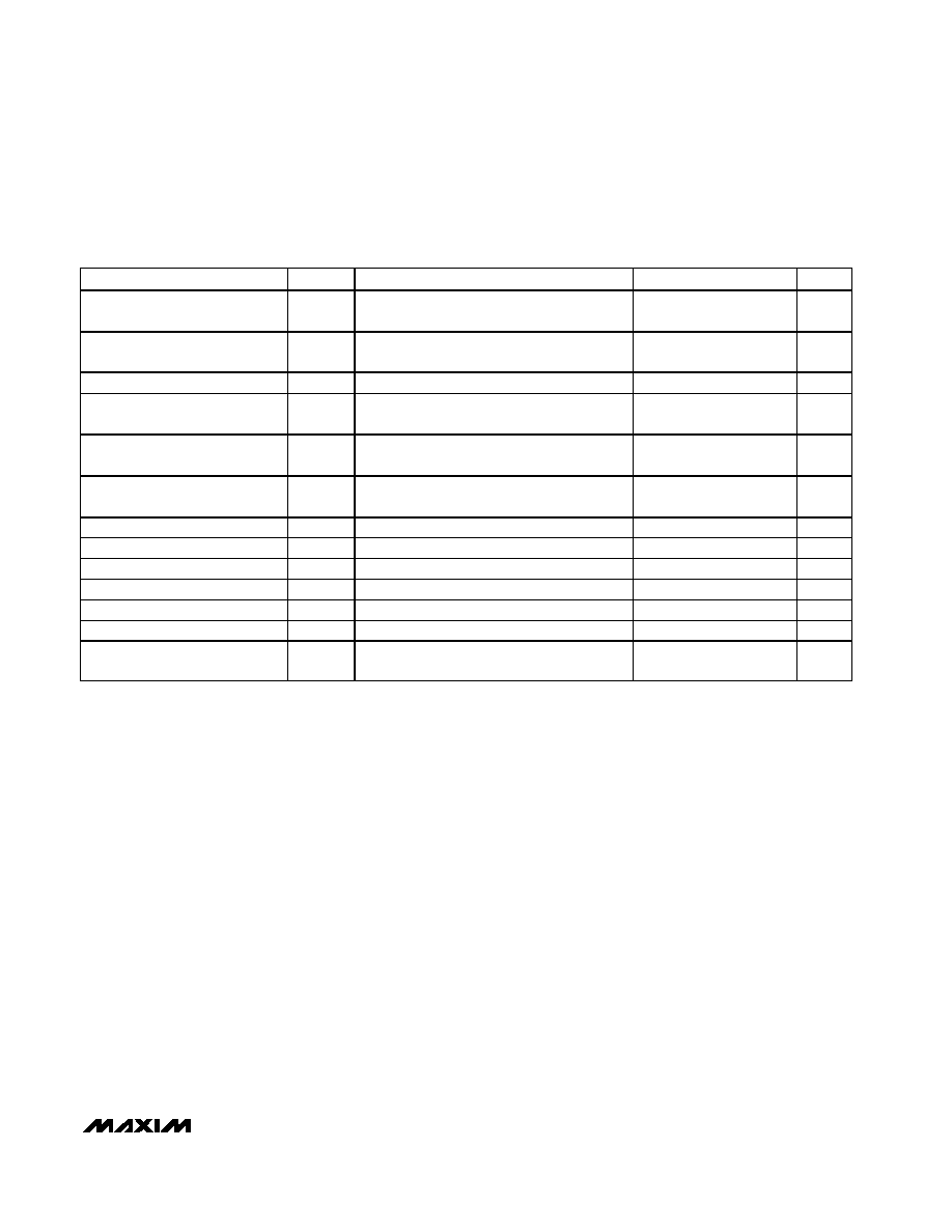
SWITCHING CHARACTERISTICS
(VCC = +3.0V to +3.6V, RL = 100
±1%, CL = 15pF, TA = -40°C to +85°C. Typical values are at VCC = +3.3V, TA = +25°C, unless
otherwise noted.) (Notes 4, 5, 6)
PARAMETER
SYMBOL
CONDITIONS
MIN
TYP
MAX
UNITS
Differential Propagation Delay
High to Low
tPHLD
Figures 2 and 3
0.7
1.7
ns
Differential Propagation Delay
Low to High
tPLHD
Figures 2 and 3
0.7
1.7
ns
Differential Pulse Skew (Note 7)
tSKD1
Figures 2 and 3
0.04
0.25
ns
Differential Channel-to-Channel
Skew (Note 8)
tSKD2
Figures 2 and 3
0.07
0.35
ns
Differential Part-to-Part Skew
(Note 9)
tSKD3
Figures 2 and 3
0.13
0.8
ns
Differential Part-to-Part Skew
(Note 10)
tSKD4
Figures 2 and 3
0.43
1.0
ns
Rise Time
tTLH
Figures 2 and 3
0.2
0.39
1.0
ns
Fall Time
tTHL
Figures 2 and 3
0.2
0.39
1.0
ns
Disable Time High to Z
tPHZ
Figures 4 and 5
2.7
5
ns
Disable Time Low to Z
tPLZ
Figures 4 and 5
2.7
5
ns
Enable Time Z to High
tPZH
Figures 4 and 5
2.3
7
ns
Enable Time Z to Low
tPZL
Figures 4 and 5
2.3
7
ns
Maximum Operating Frequency
(Note 11)
fMAX
400
MHz
Note 1: Maximum and minimum limits over temperature are guaranteed by design and characterization. Devices are 100% tested
at TA = +25°C.
Note 2: Currents into the device are positive, and current out of the device is negative. All voltages are referenced to ground except
VOD.
Note 3: Guaranteed by correlation data.
Note 4: AC parameters are guaranteed by design and characterization.
Note 5: CL includes probe and jig capacitance.
Note 6: Signal generator conditions for dynamic tests: VOL = 0, VOH = 3V, f = 100MHz, 50% duty cycle, RO = 50
, tR ≤ 1ns, tF ≤
1ns (0% to 100%).
Note 7: tSKD1 is the magnitude difference of differential propagation delay. tSKD1 = |tPHLD - tPLHD|.
Note 8: tSKD2 is the magnitude difference of tPHLD or tPLHD of one channel to the tPHLD or tPLHD of another channel on the same
device.
Note 9: tSKD3 is the magnitude difference of any differential propagation delays between devices at the same VCC and within 5°C
of each other.
Note 10: tSKD4 is the magnitude difference of any differential propagation delays between devices operating over the rated supply
and temperature ranges.
Note 11: fMAX signal generator conditions: VOL = 0, VOH = 3V, f = 400MHz, 50% duty cycle, RO = 50
, tR ≤ 1ns, tF ≤ 1ns (0% to
100%). Transmitter output criteria: duty cycle = 45% to 55%, VOD
≥ 250mV.
相关PDF资料 |
PDF描述 |
|---|---|
| MAX9124EUE+T | IC QUAD LVDS LINE DRIVER 16TSSOP |
| MAX9126EUE+T | IC QUAD LVDS LINE RCVR 16-TSSOP |
| MAX9129EUE+T | IC DRVR QUAD LVDS 16-TSSOP |
| MAX9130EXT+T | IC RCVR SNGL LVDS SC70-6 |
| MAX9150EUI+T | IC REPEATER LVDS 28-TSSOP |
相关代理商/技术参数 |
参数描述 |
|---|---|
| MAX9124 | 制造商:MAXIM 制造商全称:Maxim Integrated Products 功能描述:Quad LVDS Line Driver |
| MAX9124ESE | 功能描述:缓冲器和线路驱动器 RoHS:否 制造商:Micrel 输入线路数量:1 输出线路数量:2 极性:Non-Inverting 电源电压-最大:+/- 5.5 V 电源电压-最小:+/- 2.37 V 最大工作温度:+ 85 C 安装风格:SMD/SMT 封装 / 箱体:MSOP-8 封装:Reel |
| MAX9124ESE+ | 功能描述:LVDS 接口集成电路 Quad LVDS Line Driver RoHS:否 制造商:Texas Instruments 激励器数量:4 接收机数量:4 数据速率:155.5 Mbps 工作电源电压:5 V 最大功率耗散:1025 mW 最大工作温度:+ 85 C 封装 / 箱体:SOIC-16 Narrow 封装:Reel |
| MAX9124ESE+T | 功能描述:LVDS 接口集成电路 Quad LVDS Line Driver RoHS:否 制造商:Texas Instruments 激励器数量:4 接收机数量:4 数据速率:155.5 Mbps 工作电源电压:5 V 最大功率耗散:1025 mW 最大工作温度:+ 85 C 封装 / 箱体:SOIC-16 Narrow 封装:Reel |
| MAX9124ESE-T | 功能描述:缓冲器和线路驱动器 RoHS:否 制造商:Micrel 输入线路数量:1 输出线路数量:2 极性:Non-Inverting 电源电压-最大:+/- 5.5 V 电源电压-最小:+/- 2.37 V 最大工作温度:+ 85 C 安装风格:SMD/SMT 封装 / 箱体:MSOP-8 封装:Reel |
发布紧急采购,3分钟左右您将得到回复。