- 您现在的位置:买卖IC网 > PDF目录1945 > MAX9124EUE+T (Maxim Integrated Products)IC QUAD LVDS LINE DRIVER 16TSSOP PDF资料下载
参数资料
| 型号: | MAX9124EUE+T |
| 厂商: | Maxim Integrated Products |
| 文件页数: | 5/9页 |
| 文件大小: | 0K |
| 描述: | IC QUAD LVDS LINE DRIVER 16TSSOP |
| 产品培训模块: | Lead (SnPb) Finish for COTS Obsolescence Mitigation Program |
| 标准包装: | 2,500 |
| 类型: | 驱动器 |
| 驱动器/接收器数: | 4/0 |
| 规程: | LVDS |
| 电源电压: | 3 V ~ 3.6 V |
| 安装类型: | 表面贴装 |
| 封装/外壳: | 16-TSSOP(0.173",4.40mm 宽) |
| 供应商设备封装: | 16-TSSOP |
| 包装: | 带卷 (TR) |
MAX9124
Quad LVDS Line Driver
_______________________________________________________________________________________
5
Detailed Description
The LVDS interface standard is a signaling method
intended for point-to-point communication over a con-
trolled-impedance medium as defined by the
ANSI/TIA/EIA-644 and IEEE 1596.3 standards. The
LVDS standard uses a lower voltage swing than other
common communication standards, achieving higher
data rates with reduced power consumption while
reducing EMI emissions and system susceptibility to
noise.
The MAX9124 is an 800Mbps quad differential LVDS
driver that is designed for high-speed, point-to-point,
and low-power applications. This device accepts
LVTTL/LVCMOS input levels and translates them to
LVDS output signals.
The MAX9124 generates a 2.5mA to 4.0mA output cur-
rent using a current-steering configuration. This current-
steering approach induces less ground bounce and no
shoot-through current, enhancing noise margin and sys-
tem speed performance. The driver outputs are short-
circuit current limited and enter a high-impedance state
when the device is not powered or is disabled.
The current-steering architecture of the MAX9124
requires a resistive load to terminate the signal and
complete the transmission loop. Because the device
switches current and not voltage, the actual output volt-
age swing is determined by the value of the termination
resistor at the input of an LVDS receiver. Logic states
are determined by the direction of current flow through
the termination resistor. With a typical 3.7mA output
current, the MAX9124 produces an output voltage of
370mV when driving a 100
load.
Termination
Because the MAX9124 is a current-steering device, no
output voltage will be generated without a termination
resistor. The termination resistors should match the dif-
ferential impedance of the transmission line. Output
voltage levels depend upon the value of the termination
resistor. The MAX9124 is optimized for point-to-point
interface with 100
termination resistors at the receiver
inputs. Termination resistance values may range
between 90
and 132, depending on the characteris-
tic impedance of the transmission medium.
Applications Information
Power-Supply Bypassing
Bypass VCC with high-frequency, surface-mount
ceramic 0.1F and 0.001F capacitors in parallel as
close to the device as possible, with the smaller valued
capacitor closest to VCC.
Differential Traces
Output trace characteristics affect the performance of
the MAX9124. Use controlled-impedance traces to
match trace impedance to the transmission medium.
Eliminate reflections and ensure that noise couples as
common mode by running the differential trace pairs
close together. Reduce skew by matching the electrical
length of the traces. Excessive skew can result in a
degradation of magnetic field cancellation.
Maintain the distance between the differential traces to
avoid discontinuities in differential impedance. Avoid
90° turns and minimize the number of vias to further
prevent impedance discontinuities.
Cables and Connectors
Transmission media should have a nominal differential
impedance of 100
. To minimize impedance disconti-
nuities, use cables and connectors that have matched
differential impedance.
Avoid the use of unbalanced cables such as ribbon or
simple coaxial cable. Balanced cables, such as twisted
pair, offer superior signal quality and tend to generate
less EMI due to canceling effects. Balanced cables
tend to pick up noise as common mode, which is
rejected by the LVDS receiver.
Board Layout
For LVDS applications, a four-layer PC board that pro-
vides separate power, ground, LVDS signals, and input
signals is recommended. Isolate the LVTTL/LVCMOS
and LVDS signals from each other to prevent coupling.
Chip Information
TRANSISTOR COUNT: 2007
PROCESS: CMOS
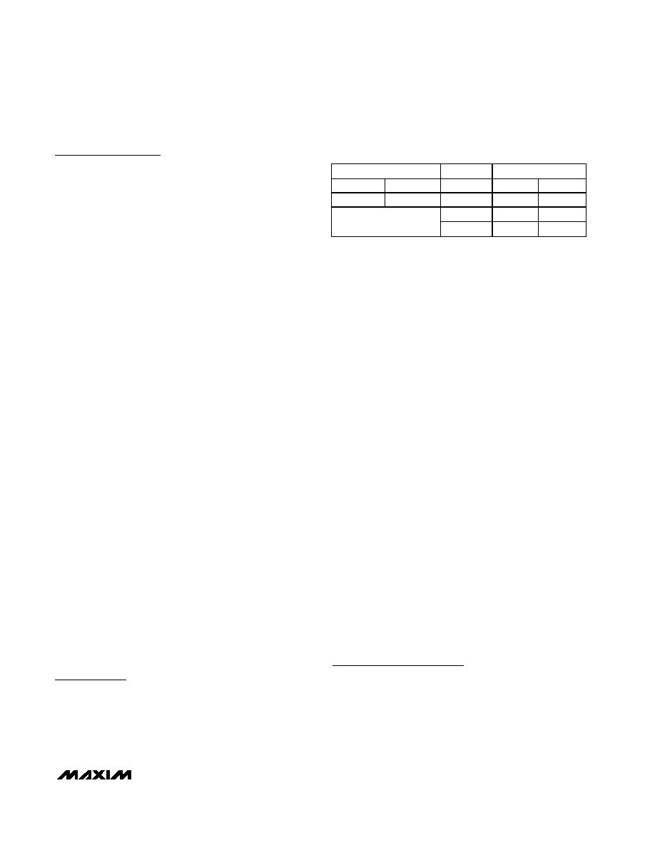
ENABLES
INPUTS
OUTPUTS
EN
EN
IN_
OUT_+
OUT_ -
LH
X
Z
LL
H
All other combinations
of ENABLE inputs
HH
L
Table 1. Input/Output Function Table
相关PDF资料 |
PDF描述 |
|---|---|
| MAX9126EUE+T | IC QUAD LVDS LINE RCVR 16-TSSOP |
| MAX9129EUE+T | IC DRVR QUAD LVDS 16-TSSOP |
| MAX9130EXT+T | IC RCVR SNGL LVDS SC70-6 |
| MAX9150EUI+T | IC REPEATER LVDS 28-TSSOP |
| MAX9152ESE+T | IC CROSSPOINT SWITCH 2X2 16SOIC |
相关代理商/技术参数 |
参数描述 |
|---|---|
| MAX9124EVKIT | 功能描述:缓冲器和线路驱动器 Evaluation Kit for the MAX9124 MAX9125 MAX9126 RoHS:否 制造商:Micrel 输入线路数量:1 输出线路数量:2 极性:Non-Inverting 电源电压-最大:+/- 5.5 V 电源电压-最小:+/- 2.37 V 最大工作温度:+ 85 C 安装风格:SMD/SMT 封装 / 箱体:MSOP-8 封装:Reel |
| MAX9125 | 制造商:MAXIM 制造商全称:Maxim Integrated Products 功能描述:Quad LVDS Line Receivers with Integrated Termination |
| MAX9125ESE | 功能描述:LVDS 接口集成电路 RoHS:否 制造商:Texas Instruments 激励器数量:4 接收机数量:4 数据速率:155.5 Mbps 工作电源电压:5 V 最大功率耗散:1025 mW 最大工作温度:+ 85 C 封装 / 箱体:SOIC-16 Narrow 封装:Reel |
| MAX9125ESE+ | 功能描述:LVDS 接口集成电路 Quad LVDS Line Driver RoHS:否 制造商:Texas Instruments 激励器数量:4 接收机数量:4 数据速率:155.5 Mbps 工作电源电压:5 V 最大功率耗散:1025 mW 最大工作温度:+ 85 C 封装 / 箱体:SOIC-16 Narrow 封装:Reel |
| MAX9125ESE+T | 功能描述:LVDS 接口集成电路 Quad LVDS Line Driver RoHS:否 制造商:Texas Instruments 激励器数量:4 接收机数量:4 数据速率:155.5 Mbps 工作电源电压:5 V 最大功率耗散:1025 mW 最大工作温度:+ 85 C 封装 / 箱体:SOIC-16 Narrow 封装:Reel |
发布紧急采购,3分钟左右您将得到回复。