- 您现在的位置:买卖IC网 > PDF目录10745 > MAX966ESA+ (Maxim Integrated Products)IC COMPARATOR R-R 8-SOIC PDF资料下载
参数资料
| 型号: | MAX966ESA+ |
| 厂商: | Maxim Integrated Products |
| 文件页数: | 2/14页 |
| 文件大小: | 0K |
| 描述: | IC COMPARATOR R-R 8-SOIC |
| 产品培训模块: | Lead (SnPb) Finish for COTS Obsolescence Mitigation Program |
| 标准包装: | 100 |
| 类型: | 通用 |
| 元件数: | 2 |
| 输出类型: | 开路漏极,满摆幅 |
| 电压 - 电源,单路/双路(±): | 1.6 V ~ 5.5 V |
| 电压 - 输入偏移(最小值): | 7mV @ 5.5V |
| 电流 - 输入偏压(最小值): | 0.05µA @ 5.5V |
| 电流 - 静态(最大值): | 10µA |
| CMRR, PSRR(标准): | 56.48dB CMRR,80dB PSRR |
| 传输延迟(最大): | 20µs |
| 磁滞: | ±1mV |
| 工作温度: | -40°C ~ 85°C |
| 封装/外壳: | 8-SOIC(0.154",3.90mm 宽) |
| 安装类型: | 表面贴装 |
| 包装: | 管件 |
| 产品目录页面: | 1386 (CN2011-ZH PDF) |
MAX965–MAX970
Single/Dual/Quad, Micropower,
Ultra-Low-Voltage, Rail-to-Rail I/O Comparators
10
______________________________________________________________________________________
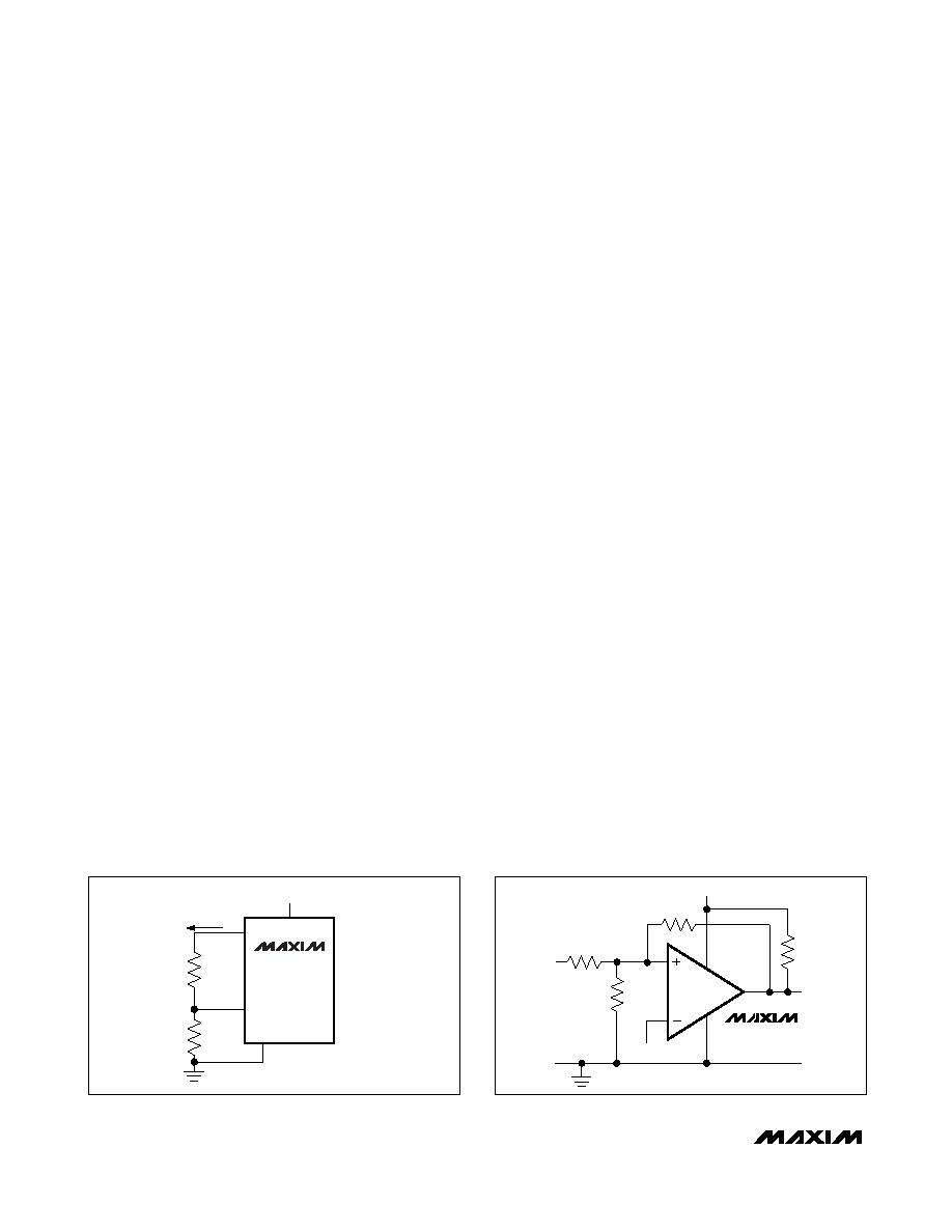
HYST
REF
GND
VCC
R1
R2
MAX965
MAX967
MAX968
MAX969
+1.6V TO +5.5V
IREF
Figure 3. Programming the HYST Pin
GND
VCC
OUT
R3
R1
R2
R4
VREF
VIN
MAX966
MAX970
Figure 4. External Hysteresis
Figure 2 illustrates the case in which IN- has a fixed
voltage applied, and IN+ is varied. If the inputs were
reversed, the figure would be the same, except with an
inverted output.
Adding Hysteresis to the
MAX965/MAX967/MAX968/MAX969
To add hysteresis to the MAX965/MAX967/MAX968/
MAX969, connect resistor R1 between REF and HYST,
and connect resistor R2 between HYST and GND
(Figure 3). If additional hysteresis is not required,
connect HYST to REF. When hysteresis is added, the
upper and lower trip points change by the same
amount in opposite directions. The hysteresis band (the
difference between the upper and lower trip points,
VHB) is approximately twice the voltage between HYST
and REF. The HYST input voltage range is from REF
down to (REF - 50mV). This yields a hysteresis band
from ±1mV to a maximum of ±50mV. Calculate the val-
ues of R1 and R2 for the desired hysteresis band with
the following formulas:
R1 = VHB / IREF
R2 = (VREF - VHB) / IREF
where IREF (the current sourced by the reference) does
not exceed the REF source capability (12A typical),
and is significantly larger than the HYST leakage cur-
rent (5nA typical). IREF values between 0.1A and 4A
are good choices. If 2.4M is chosen for R2 (IREF =
0.5A), the equation for R1 and VHB can be approxi-
mated as:
R1(k) = 2 x VHB (mV)
In the MAX967/MAX968/MAX969, the HYST pin pro-
grams the same hysteresis for all comparators in the
package.
Due to the internal structure of the input developed for
ultra-low-voltage operation, the hysteresis band varies
with common-mode voltage. The graph Programmed
Hysteresis vs. Common-Mode Voltage in the Typical
Operating Characteristics shows this variation. Notice
that the hysteresis band increases to almost twice the
calculated value toward the ends of the common-mode
range. This is apparent only when programming addi-
tional hysteresis using the HYST pin. The hysteresis
band is constant when HYST is connected to REF.
Adding Hysteresis to the MAX966/MAX970
The MAX966/MAX970 do not have a HYST pin for pro-
gramming hysteresis. Hysteresis can be generated with
three resistors using positive feedback (Figure 4). This
method generally draws more current than the method
using the HYST pin on the MAX965/MAX967/MAX968/
MAX969. Also, the positive feedback method slows
hysteresis response time. Use the following procedure
to calculate the resistor values:
1) Select R3. The leakage current of IN+ is under 5nA,
so the current through R3 should be at least 500nA
to minimize errors caused by leakage current. The
current through R3 at the trip point is (VREF - VOUT) /
R3. Taking into consideration the two possible out-
put states and solving for R3 yields two formulas:
R3 = VREF / 500nA
and
R3 = (VREF - VCC) / 500nA
Use the smaller of the two resulting resistor values.
For example, if VREF = 1.2V and VCC = 5.0V, then
the two resistor values are 2.4M and 7.6m. For
R3, choose the 2.2M standard value.
2) Choose the hysteresis band required (VHB). For this
example, choose 50mV.
相关PDF资料 |
PDF描述 |
|---|---|
| VE-JN4-MY-F1 | CONVERTER MOD DC/DC 48V 50W |
| MAX965ESA+ | IC COMPARATOR R-R 8-SOIC |
| VE-JN3-MY-F4 | CONVERTER MOD DC/DC 24V 50W |
| MAX966EUA+ | IC COMPARATOR R-R 8-UMAX |
| VI-J6K-MW-F4 | CONVERTER MOD DC/DC 40V 100W |
相关代理商/技术参数 |
参数描述 |
|---|---|
| MAX966ESA+ | 功能描述:校验器 IC Dual uPower Comparator RoHS:否 制造商:STMicroelectronics 产品: 比较器类型: 通道数量: 输出类型:Push-Pull 电源电压-最大:5.5 V 电源电压-最小:1.1 V 补偿电压(最大值):6 mV 电源电流(最大值):1350 nA 响应时间: 最大工作温度:+ 125 C 安装风格:SMD/SMT 封装 / 箱体:SC-70-5 封装:Reel |
| MAX966ESA+T | 功能描述:校验器 IC Dual uPower Comparator RoHS:否 制造商:STMicroelectronics 产品: 比较器类型: 通道数量: 输出类型:Push-Pull 电源电压-最大:5.5 V 电源电压-最小:1.1 V 补偿电压(最大值):6 mV 电源电流(最大值):1350 nA 响应时间: 最大工作温度:+ 125 C 安装风格:SMD/SMT 封装 / 箱体:SC-70-5 封装:Reel |
| MAX966ESA-T | 功能描述:校验器 IC Dual uPower Comparator RoHS:否 制造商:STMicroelectronics 产品: 比较器类型: 通道数量: 输出类型:Push-Pull 电源电压-最大:5.5 V 电源电压-最小:1.1 V 补偿电压(最大值):6 mV 电源电流(最大值):1350 nA 响应时间: 最大工作温度:+ 125 C 安装风格:SMD/SMT 封装 / 箱体:SC-70-5 封装:Reel |
| MAX966EUA | 功能描述:校验器 IC Dual uPower Comparator RoHS:否 制造商:STMicroelectronics 产品: 比较器类型: 通道数量: 输出类型:Push-Pull 电源电压-最大:5.5 V 电源电压-最小:1.1 V 补偿电压(最大值):6 mV 电源电流(最大值):1350 nA 响应时间: 最大工作温度:+ 125 C 安装风格:SMD/SMT 封装 / 箱体:SC-70-5 封装:Reel |
| MAX966EUA+ | 功能描述:校验器 IC Dual uPower Comparator RoHS:否 制造商:STMicroelectronics 产品: 比较器类型: 通道数量: 输出类型:Push-Pull 电源电压-最大:5.5 V 电源电压-最小:1.1 V 补偿电压(最大值):6 mV 电源电流(最大值):1350 nA 响应时间: 最大工作温度:+ 125 C 安装风格:SMD/SMT 封装 / 箱体:SC-70-5 封装:Reel |
发布紧急采购,3分钟左右您将得到回复。