- 您现在的位置:买卖IC网 > PDF目录10466 > MAX9705CETB+T (Maxim Integrated Products)IC AMP AUDIO PWR 2.3W D 10TDFN PDF资料下载
参数资料
| 型号: | MAX9705CETB+T |
| 厂商: | Maxim Integrated Products |
| 文件页数: | 5/18页 |
| 文件大小: | 0K |
| 描述: | IC AMP AUDIO PWR 2.3W D 10TDFN |
| 产品培训模块: | Lead (SnPb) Finish for COTS Obsolescence Mitigation Program |
| 标准包装: | 1 |
| 类型: | D 类 |
| 输出类型: | 1-通道(单声道) |
| 在某负载时最大输出功率 x 通道数量: | 2.3W x 1 @ 4 欧姆 |
| 电源电压: | 2.5 V ~ 5.5 V |
| 特点: | 消除爆音,差分输入,短路和热保护,关闭 |
| 安装类型: | 表面贴装 |
| 供应商设备封装: | 10-TDFN-EP(3x3) |
| 封装/外壳: | 10-WFDFN 裸露焊盘 |
| 包装: | 标准包装 |
| 其它名称: | MAX9705CETB+TDKR |
MAX9705
2.3W, Ultra-Low-EMI, Filterless,
Class D Audio Amplifier
______________________________________________________________________________________
13
Note that the single-ended voltage range of the
MAX9705A is 3VP-P. This limits the achievable output
power for this device. Use higher gain versions
(MAX9705B, MAX9705C, MAX9705D) if higher output
power is desired in a single-ended application.
DC-Coupled Input
The input amplifier can accept DC-coupled inputs that
are biased within the amplifier’s common-mode range
(see the
Typical Operating Characteristics). DC cou-
pling eliminates the input-coupling capacitors, reduc-
ing component count to potentially one external
component (see the
System Diagram). However, the
low-frequency rejection of the capacitors is lost, allow-
ing low-frequency signals to feed through to the load.
Component Selection
Input Filter
An input capacitor, CIN, in conjunction with the input
resistance of the MAX9705 forms a highpass filter that
removes the DC bias from an incoming signal. The AC-
coupling capacitor allows the amplifier to bias the sig-
nal to an optimum DC level. Assuming zero source
impedance, the -3dB point of the highpass filter is
given by:
Choose CIN so f-3dB is well below the lowest frequency
of interest. Setting f-3dB too high affects the low-
frequency response of the amplifier. Use capacitors
whose dielectrics have low-voltage coefficients, such
as tantalum or aluminum electrolytic. Capacitors with
high-voltage coefficients, such as ceramics, may result
in increased distortion at low frequencies. If a ceramic
capacitor is selected due to size constraints, use the
largest package possible to minimize voltage coeffi-
cient effects. In addition, use X7R dielectrics as
opposed to Y5V or Z5U.
Other considerations when designing the input filter
include the constraints of the overall system and the
actual frequency band of interest. Although high-fidelity
audio calls for a flat gain response between 20Hz and
20kHz, portable voice-reproduction devices such as
cellular phones and two-way radios need only concen-
trate on the frequency range of the spoken human
voice (typically 300Hz to 3.5kHz). In addition, speakers
used in portable devices typically have a poor response
below 150Hz. Taking these two factors into considera-
tion, the input filter may not need to be designed for a
20Hz to 20kHz response, saving both board space and
cost due to the use of smaller capacitors.
Output Filter
The MAX9705 does not require an output filter. The
device passes FCC emissions standards with 24in of
unshielded twisted-pair speaker cables. However, an
output filter can be used if a design is failing radiated
emissions due to board layout or excessive cable
length, or the circuit is near EMI-sensitive devices.
Supply Bypassing/Layout
Proper power-supply bypassing ensures low-distortion
operation. For optimum performance, bypass VDD to
GND and PVDD to PGND with separate 1F capacitors
as close to each pin as possible. A low-impedance,
high-current power-supply connection to PVDD is
assumed. Additional bulk capacitance should be added
as required depending on the application and power-
supply characteristics. GND and PGND should be star
connected to system ground. Refer to the MAX9705
evaluation kit for layout guidance.
Stereo Configuration
Two MAX9705s can be configured as a stereo amplifier
(Figure 6). Device U1 is the master amplifier; its unfil-
tered output drives the SYNC input of the slave device
(U2), synchronizing the switching frequencies of the two
devices. Synchronizing two MAX9705s ensures that no
beat frequencies occur within the audio spectrum. This
configuration works when the master device is in either
FFM or SSM mode. There is excellent THD+N perfor-
mance and minimal crosstalk between devices due to
the SYNC connection (Figures 7 and 8). U2 locks onto
only the frequency present at SYNC, not the pulse
width. The internal feedback loop of device U2 ensures
that the audio component of U1’s output is rejected.
f
RC
dB
IN
=
3
1
2
π
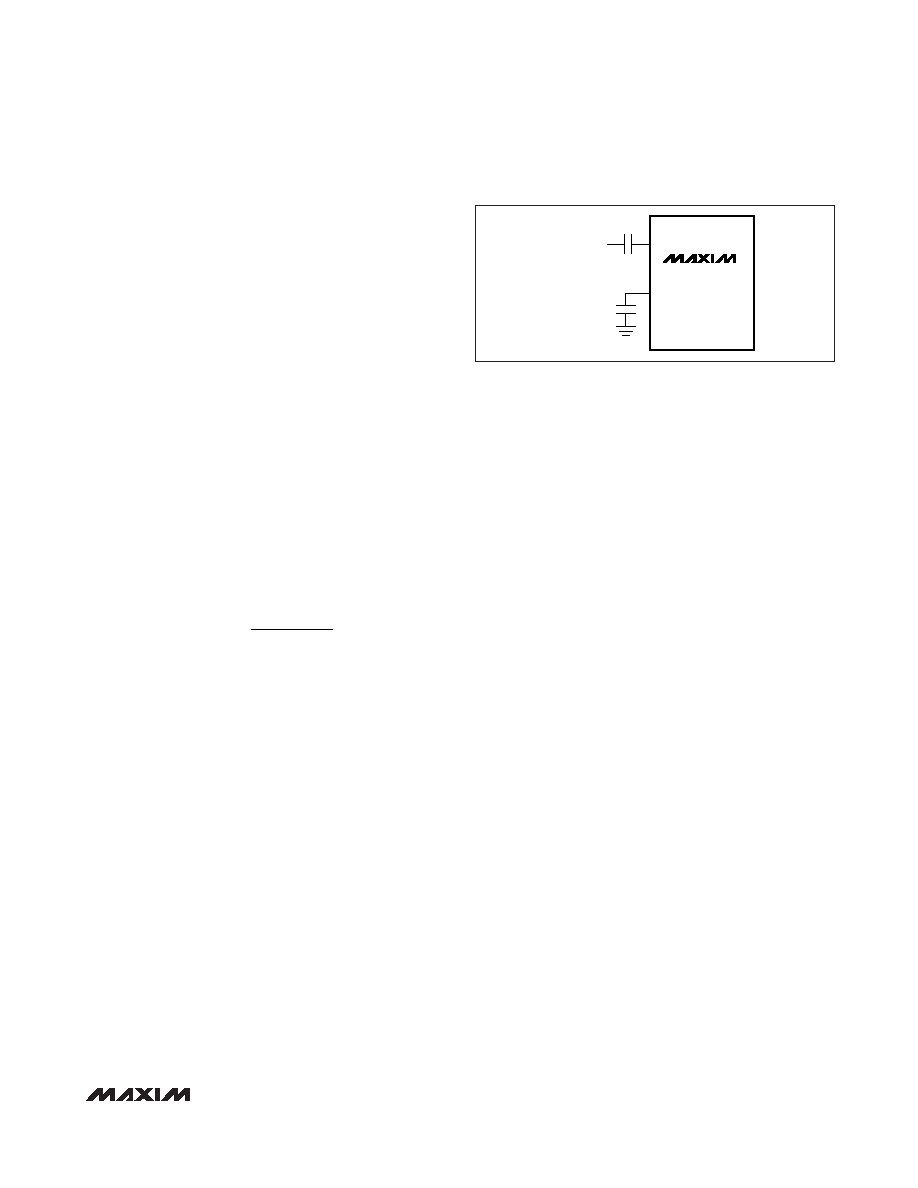
Figure 5. Single-Ended Input
1
F
IN+
IN-
1
F
SINGLE-ENDED
AUDIO INPUT
MAX9705
相关PDF资料 |
PDF描述 |
|---|---|
| VE-2TV-IW-F2 | CONVERTER MOD DC/DC 5.8V 100W |
| MCP3302T-BI/ST | IC ADC 13BIT 2.7V 2CH SPI14TSSOP |
| VE-J4V-MW-F1 | CONVERTER MOD DC/DC 5.8V 100W |
| MCP3302-BI/ST | IC ADC 13BIT 2.7V 2CH SPI14TSSOP |
| VE-2TT-IW-F4 | CONVERTER MOD DC/DC 6.5V 100W |
相关代理商/技术参数 |
参数描述 |
|---|---|
| MAX9705DEBC+ | 制造商:Rochester Electronics LLC 功能描述: 制造商:Maxim Integrated Products 功能描述: |
| MAX9705DEBC+T | 功能描述:音频放大器 2.3W Ultra-Low-EMI Class D Amplifier RoHS:否 制造商:STMicroelectronics 产品:General Purpose Audio Amplifiers 输出类型:Digital 输出功率: THD + 噪声: 工作电源电压:3.3 V 电源电流: 最大功率耗散: 最大工作温度: 安装风格:SMD/SMT 封装 / 箱体:TQFP-64 封装:Reel |
| MAX9705DETB+ | 制造商:Maxim Integrated Products 功能描述:AUD AMP SPKR 1CH MONO 2.3W CLS-D 10TDFN EP - Rail/Tube |
| MAX9705DETB+T | 功能描述:音频放大器 2.3W Ultra-Low-EMI Class D Amplifier RoHS:否 制造商:STMicroelectronics 产品:General Purpose Audio Amplifiers 输出类型:Digital 输出功率: THD + 噪声: 工作电源电压:3.3 V 电源电流: 最大功率耗散: 最大工作温度: 安装风格:SMD/SMT 封装 / 箱体:TQFP-64 封装:Reel |
| MAX9706ETX+ | 功能描述:音频放大器 Integrated Circuits (ICs) RoHS:否 制造商:STMicroelectronics 产品:General Purpose Audio Amplifiers 输出类型:Digital 输出功率: THD + 噪声: 工作电源电压:3.3 V 电源电流: 最大功率耗散: 最大工作温度: 安装风格:SMD/SMT 封装 / 箱体:TQFP-64 封装:Reel |
发布紧急采购,3分钟左右您将得到回复。