- 您现在的位置:买卖IC网 > PDF目录10459 > MAX9708ETN+D (Maxim Integrated Products)IC AMP AUDIO PWR 42W STER 56TQFN PDF资料下载
参数资料
| 型号: | MAX9708ETN+D |
| 厂商: | Maxim Integrated Products |
| 文件页数: | 5/22页 |
| 文件大小: | 0K |
| 描述: | IC AMP AUDIO PWR 42W STER 56TQFN |
| 产品培训模块: | Lead (SnPb) Finish for COTS Obsolescence Mitigation Program |
| 标准包装: | 37 |
| 类型: | D 类 |
| 输出类型: | 1-通道(单声道)或 2-通道(立体声) |
| 在某负载时最大输出功率 x 通道数量: | 42W x 1 @ 4 欧姆; 21W x 2 @ 8 欧姆 |
| 电源电压: | 10 V ~ 18 V |
| 特点: | 消除爆音,差分输入,静音,短路和热保护,关机 |
| 安装类型: | 表面贴装 |
| 供应商设备封装: | 56-TQFN-EP(8x8) |
| 封装/外壳: | 56-WFQFN 裸露焊盘 |
| 包装: | 管件 |
| 产品目录页面: | 1392 (CN2011-ZH PDF) |
MAX9708
20W/40W, Filterless, Spread-Spectrum,
Mono/Stereo, Class D Amplifier
13
Maxim Integrated
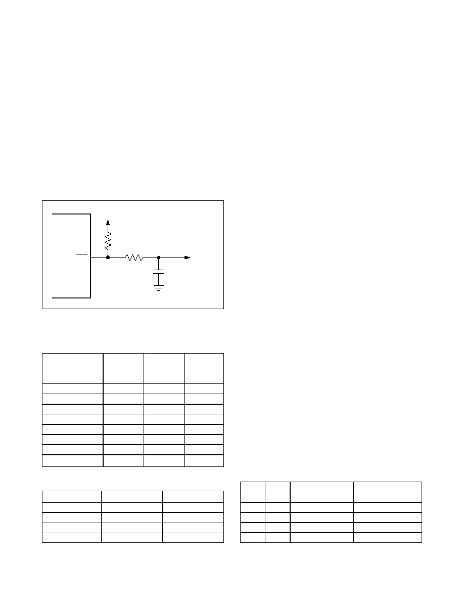
TEMP returns high once the junction temperature cools
below the set threshold minus the thermal hysteresis. If
TEMP is connected to either MUTE or SS, the audio
output resumes. The temperature threshold is set by
the TH0, TH1, and TH2 inputs as shown in Table 1. An
RC filter may be used to eliminate any transient at the
TEMP output as shown in Figure 3.
Gain Selection
The MAX9708 features four pin-selectable gain settings;
see Table 2.
Operating Modes
Fixed-Frequency Modulation (FFM) Mode
The MAX9708 features three switching frequencies in
the FFM mode (Table 3). In this mode, the frequency
spectrum of the Class D output consists of the funda-
mental switching frequency and its associated harmon-
ics (see the Wideband Output Spectrum graph in the
Typical Operating Characteristics). Select one of the
three fixed switching frequencies such that the harmon-
ics do not fall in a sensitive band. The switching fre-
quency can be changed at any time without affecting
audio reproduction.
Spread-Spectrum Modulation (SSM) Mode
The MAX9708 features a unique spread-spectrum
(SSM) mode that flattens the wideband spectral com-
ponents, improving EMI emissions that may be radiated
by the speaker and cables. This mode is enabled by
setting FS1 = FS2 = high. In SSM mode, the switching
frequency varies randomly by ±4% around the center
frequency (200kHz). The modulation scheme remains
the same, but the period of the triangle waveform
changes from cycle to cycle. Instead of a large amount
of spectral energy present at multiples of the switching
frequency, the energy is now spread over a bandwidth
that increases with frequency. Above a few megahertz,
the wideband spectrum looks like white noise for EMI
purposes. SSM mode reduces EMI compared to fixed-
frequency mode. This can also help to randomize visu-
al artifacts caused by radiated or supply-borne
interference in displays.
Synchronous Switching Mode
The MAX9708 SYNCIN input allows the Class D amplifi-
er to switch at a frequency defined by an external clock
frequency. Synchronizing the amplifier with an external
clock source may confine the switching frequency to a
less sensitive band. The external clock frequency range
is from 600kHz to 1.2MHz and can have any duty cycle,
but the minimum pulse must be greater than 100ns.
SYNCOUT is an open-drain clock output for synchro-
nizing external circuitry. Its frequency is four times the
amplifier’s switching frequency, and it is active in either
internal or external oscillator mode.
Figure 3. An RC Filter Eliminates Transient During Switching
Table 1. MAX9708 Junction Temperature
Threshold Setting
TEMP
0.1
μF
10k
Ω
10k
Ω
VDIGITAL
TO DIGITAL
INPUT
JUNCTION
TEMPERATURE
(°C)
TH2
TH1
TH0
80
Low
90
Low
High
100
Low
High
Low
110
Low
High
120
High
Low
129
High
Low
High
139
High
Low
150
High
Table 2. MAX9708 Gain Setting
G1
G2
GAIN (dB)
Low
High
22
High
25
High
Low
29.5
Low
36
Table 3. Switching Frequencies
FS1
FS2
SYNCOUT
FREQUENCY (kHz)
MODULATION
0
200
Fixed-Frequency
0
1
250
Fixed-Frequency
1
0
160
Fixed-Frequency
1
200 ±4
Spread-Spectrum
相关PDF资料 |
PDF描述 |
|---|---|
| VJ1210Y101MXPAT5Z | CAP CER 100PF 250V 20% X7R 1210 |
| MS27473T10B98SA | CONN PLUG 6POS STRAIGHT W/SCKT |
| VE-21Y-IU-F2 | CONVERTER MOD DC/DC 3.3V 132W |
| VE-B5X-IV-F4 | CONVERTER MOD DC/DC 5.2V 150W |
| VJ1210Y101KXLAT5Z | CAP CER 100PF 630V 10% X7R 1210 |
相关代理商/技术参数 |
参数描述 |
|---|---|
| MAX9708ETN-T | 制造商:Maxim Integrated Products 功能描述:20W/40W FILTERLESS, SPREAD-SPECTRUM, MONO/STE - Tape and Reel |
| MAX9708EVKIT | 功能描述:音频放大器 Evaluation Kit for the MAX9708 RoHS:否 制造商:STMicroelectronics 产品:General Purpose Audio Amplifiers 输出类型:Digital 输出功率: THD + 噪声: 工作电源电压:3.3 V 电源电流: 最大功率耗散: 最大工作温度: 安装风格:SMD/SMT 封装 / 箱体:TQFP-64 封装:Reel |
| MAX9709ECB+ | 制造商:Maxim Integrated Products 功能描述:AUD AMP SPKR 1CH MONO/2CH STEREO 50W/29W CLS-D 64TQFP EP - Rail/Tube |
| MAX9709ECB+T | 制造商:Maxim Integrated Products 功能描述:AUD AMP SPKR 1CH MONO/2CH STEREO 50W/29W CLS-D 64TQFP EP - Tape and Reel |
| MAX9709ETN | 功能描述:音频放大器 RoHS:否 制造商:STMicroelectronics 产品:General Purpose Audio Amplifiers 输出类型:Digital 输出功率: THD + 噪声: 工作电源电压:3.3 V 电源电流: 最大功率耗散: 最大工作温度: 安装风格:SMD/SMT 封装 / 箱体:TQFP-64 封装:Reel |
发布紧急采购,3分钟左右您将得到回复。