- 您现在的位置:买卖IC网 > PDF目录2091 > MAX97200AEWC+T (Maxim Integrated Products)IC HEADPHONE AMPLIFIER 12WLP PDF资料下载
参数资料
| 型号: | MAX97200AEWC+T |
| 厂商: | Maxim Integrated Products |
| 文件页数: | 2/13页 |
| 文件大小: | 0K |
| 描述: | IC HEADPHONE AMPLIFIER 12WLP |
| 产品培训模块: | Lead (SnPb) Finish for COTS Obsolescence Mitigation Program |
| 标准包装: | 1 |
| 系列: | DirectDrive® |
| 类型: | H 类 |
| 输出类型: | 耳机,2-通道(立体声) |
| 在某负载时最大输出功率 x 通道数量: | 45mW x 2 @ 16 欧姆 |
| 电源电压: | 1.62 V ~ 1.98 V |
| 特点: | 消除爆音;关闭 |
| 安装类型: | 表面贴装 |
| 供应商设备封装: | 12-WLP |
| 封装/外壳: | 12-WFBGA,WLCSP |
| 包装: | 标准包装 |
| 其它名称: | MAX97200AEWC+TDKR |
Low-Power, Low-Offset, Dual Mode, Class H
DirectDrive Headphone Amplifier
MAX97200
10
RIN is the amplifier’s input resistance value. Choose CIN
such that f-3dB is well below the lowest frequency of
interest. Setting f-3dB too high affects the amplifier’s low
frequency. Capacitors with higher voltage coefficients,
such as ceramics, result in increased distortion at low
frequencies.
Charge-Pump Capacitor Selection
Use capacitors with an ESR less than 100mI for opti-
mum performance. Low ESR ceramic capacitors mini-
mize the output resistance of the charge pump. For best
performance over the extended temperature range,
select capacitors with an X7R dielectric.
Flying Capacitor (C1)
The value of the flying capacitor (C1) affects the load
regulation and output resistance of the charge pump. A
C1 value that is too small degrades the device’s ability
to provide sufficient current drive, which leads to a loss
of output voltage. Connect a 1FF capacitor between C1P
and C1N.
Output Capacitors (C2, C3)
The output capacitor value and ESR directly affect the
ripple at PVSS. Increasing the value of C2 and C3 reduc-
es output ripple. Likewise, decreasing the ESR of C2 and
C3 reduces both ripple and output resistance. Lower
capacitance values can be used in systems with low
maximum output power levels. Connect a 1FF capaci-
tor between PVDD and PGND. Connect a 1FF capacitor
between PVSS and PGND.
RF Susceptibility
Improvements to both layout and component selec-
tion can decrease the MAX97200 susceptibility to RF
noise and prevent RF signals from being demodulated
into audible noise. Trace lengths should be kept below
of the wavelength of the RF frequency of interest.
Minimizing the trace lengths prevents the traces from
functioning as antennas and coupling RF signals into the
MAX97200. The wavelength (λ) in meters is given by:
λ
= c/f
where c = 3 x 10⁸ m/s, and f is the RF frequency of
interest.
Route audio signals to the middle layers of the PCB to
allow the ground planes above and below to shield them
from RF interference. Ideally, the top and bottom layers
of the PCB should primarily be ground planes to create
effective shielding.
Additional RF immunity can also be obtained from rely-
ing on the self-resonant frequency of capacitors as
it exhibits the frequency response similar to a notch
filter. Depending on the manufacturer, 10pF to 20pF
capacitors typically exhibit self resonance at RF frequen-
cies. These capacitors when placed at the input pins
can effectively shunt the RF noise at the inputs of the
MAX97200. For these capacitors to be effective, provide
a low-impedance, low-inductance path from the capaci-
tors to the ground plane. Do not use microvias to con-
nect to the ground plane as these vias do not conduct
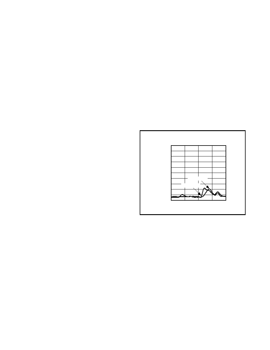
well at RF frequencies. Figure 3 shows headphone RF
immunity with a well laid out PCB.
Layout and Grounding
Proper layout and grounding are essential for optimum
performance. Use large traces for the power-supply
inputs and amplifier outputs to minimize losses due to
parasitic trace resistance, as well as route heat away
from the device. Good grounding improves audio per-
formance, minimizes crosstalk between channels, and
prevents switching noise from coupling into the audio
signal. Connect PGND and GND together at a single
point on the PCB. Route PGND and all traces that carry
switching transients away from GND, and the traces and
components in the audio signal path.
Connect C2 to the PGND plane. Place the charge-pump
capacitors (C1, C2) as close as possible to the device.
Bypass PVDD with a 1FF capacitor to PGND. Place the
bypass capacitors as close as possible to the device.
Figure 3. Headphone RF Immunity
HEADPHONE RF IMMUNITY
vs. FREQUENCY
FREQUENCY (MHz)
OUTPUT
NOISE
(dBV)
2500
2000
1500
-90
-80
-70
-60
-50
-40
-30
-20
-10
0
-100
1000
3000
LEFT CHANNEL
RIGHT CHANNEL
相关PDF资料 |
PDF描述 |
|---|---|
| MAX9720AEUE+T | IC AMP AUDIO .05W STER 16TSSOP |
| MAX97220DETE+ | IC AUDIO AMP HEADPHONE 16TQFN |
| MAX9722AETE+G | IC AMP AUDIO .13W STER AB 16TQFN |
| MAX9723CETE+ | IC AMP AUDIO .06W STER AB 16TQFN |
| MAX9724AEUD+ | IC AMP AUDIO .045W STER 14TSSOP |
相关代理商/技术参数 |
参数描述 |
|---|---|
| MAX97200BEWC+T | 功能描述:音频放大器 Class H DirectDrive Headphone Amplifier RoHS:否 制造商:STMicroelectronics 产品:General Purpose Audio Amplifiers 输出类型:Digital 输出功率: THD + 噪声: 工作电源电压:3.3 V 电源电流: 最大功率耗散: 最大工作温度: 安装风格:SMD/SMT 封装 / 箱体:TQFP-64 封装:Reel |
| MAX9720AEBE | 制造商:Maxim Integrated Products 功能描述:50MW, DIRECTDRIVE, STEREO HEADPHONE AMPLIFIER - Rail/Tube |
| MAX9720AEBE+ | 制造商:Maxim Integrated Products 功能描述:AUD AMP HDPH 2CH STEREO 0.05W CLS-AB 16UCSP - Rail/Tube |
| MAX9720AEBE+T | 功能描述:音频放大器 50mW DirectDrive Headphone Amplifier RoHS:否 制造商:STMicroelectronics 产品:General Purpose Audio Amplifiers 输出类型:Digital 输出功率: THD + 噪声: 工作电源电压:3.3 V 电源电流: 最大功率耗散: 最大工作温度: 安装风格:SMD/SMT 封装 / 箱体:TQFP-64 封装:Reel |
| MAX9720AEBE-T | 功能描述:音频放大器 RoHS:否 制造商:STMicroelectronics 产品:General Purpose Audio Amplifiers 输出类型:Digital 输出功率: THD + 噪声: 工作电源电压:3.3 V 电源电流: 最大功率耗散: 最大工作温度: 安装风格:SMD/SMT 封装 / 箱体:TQFP-64 封装:Reel |
发布紧急采购,3分钟左右您将得到回复。