- 您现在的位置:买卖IC网 > PDF目录2091 > MAX9738EWP+TG45 (Maxim Integrated Products)IC AMP AUDIO PWR MONO G 20WLP PDF资料下载
参数资料
| 型号: | MAX9738EWP+TG45 |
| 厂商: | Maxim Integrated Products |
| 文件页数: | 3/14页 |
| 文件大小: | 0K |
| 描述: | IC AMP AUDIO PWR MONO G 20WLP |
| 产品培训模块: | Lead (SnPb) Finish for COTS Obsolescence Mitigation Program |
| 标准包装: | 2,500 |
| 类型: | G 类 |
| 输出类型: | 1-通道(单声道) |
| 电源电压: | 2.7 V ~ 5.5 V |
| 特点: | 消除爆音,差分输入,关闭 |
| 安装类型: | 表面贴装 |
| 供应商设备封装: | 20-WLP |
| 封装/外壳: | 20-WFBGA,WLBGA |
| 包装: | 带卷 (TR) |
| 配用: | MAX9738EVKIT+-ND - KIT EVALUATION FOR MAX9738 |
Component Selection
Input Coupling Capacitors (CIN_)
The AC-coupling capacitors (CIN_) and input resistors
(RIN_) form highpass filters that remove any DC bias from
an input signal (see the
Typical Application Circuit/
Functional Diagram). CIN_ blocks the input signal source
from appearing at the amplifier outputs. The -3dB point of
the highpass filter, assuming zero source impedance due
to the input signal source, is given by:
Ceramic speakers generally perform best at frequen-
cies greater than 1kHz. To reduce low-frequency dis-
tortion that may be added by the ceramic speakers
low-frequency response, select a CIN such that the
f-3dB closely matches the low-frequency response of
the ceramic speaker. Use capacitors with low-voltage
coefficient dielectrics. Aluminum electrolytic, tantalum,
or film dielectric capacitors are good choices for AC-
coupling capacitors. Capacitors with high-voltage coef-
ficients, such as ceramics (non-C0G dielectrics), can
result in increased distortion at low frequencies.
Boost Converter Output Capacitor Selection (C1)
The total output voltage ripple has two components: the
capacitive ripple caused by the charging and
discharging of the output capacitance, and the voltage
drop across the capacitor’s ESR caused by the current
into and out of the capacitor. The worst-case voltage
ripple is:
where IL_RIPPLE is the inductor ripple current. For
ceramic capacitors, the output voltage ripple is typically
dominated by VVSS_RIPPLE(C). The voltage rating and
temperature characteristics of the output capacitor must
also be considered. Note that all ceramic capacitors
typically have large temperature coefficients and bias
voltage coefficients. The actual capacitor value in the
circuit is typically significantly less than the stated value.
Input Filter Capacitor (C2)
The input capacitor reduces the current peaks drawn
from the input supply and reduces noise injection into
the IC. A 10μF ceramic capacitor is recommended for
the
Typical Applications Circuit/Functional Diagram
because of the high-source impedance seen in typical
lab setups. Actual applications usually have much
lower source impedance since the step-up regulator
often runs directly from a battery. Typically, the input
capacitance can be reduced below 10μF.
Boost Flying Capacitor (C3)
A bootstrap circuit that uses an external flying capaci-
tor between LX and BST provides the supply voltage
for the internal n-channel MOSFET driver. A 0.1μF or
larger ceramic capacitor provides sufficient current for
the internal MOSFET driver supply.
Inductor Selection
The MAX9738 operates with a standard 2.2μH inductor
for the entire range of supply voltages and load cur-
rents. The inductor must have a saturation (incremen-
tal) current (ISAT) rating greater than the peak switching
current. Choose an inductor that has a higher ISAT rat-
ing than the given FET Current Limit (Transient) specifi-
cation in the
Electrical Characteristics table.
Temperature characteristics of the inductor’s saturation
current must also be considered.
VV
V
I
2C
V
VI
R
I
V
1
VSS_RIPPLE
VSS_RIPPLE(C)
VSS_RIPPLE(ESR)
VSS_RIPPLE(C)
L_RIPPLE2
SS
VSS_RIPPLE(ESR)
L_RIPPLE(ESR)
ESR
L_RIPPLE
BAT
=+
=
×
××
×
=×
L
t
and
where
L
t
FON
1
f dB
Hz
=
××
()
3
1
2R
C
IN
π
MAX9738
16VP-P Class G Amplifier with
Inverting Boost Converter
______________________________________________________________________________________
11
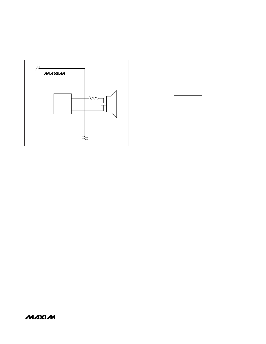
MAX9738
OUT+
RL
OUT-
CLASS G
OUTPUT
STAGE
Figure 3. Driving a Ceramic Speaker
相关PDF资料 |
PDF描述 |
|---|---|
| MAX973ESA+ | IC COMPARATOR OD 8-SOIC |
| MAX9741ETN+D | IC AMP AUDIO PWR 12W STER 56TQFN |
| MAX9742ETX+ | IC AMP AUDIO PWR 20.5W D 36TQFN |
| MAX9744ETH+ | IC AMP AUDIO PWR 22.5W D 44TQFN |
| MAX9753ETI+T | IC AMP AUDIO PWR 2.2W D 28TQFN |
相关代理商/技术参数 |
参数描述 |
|---|---|
| MAX973C/D | 功能描述:校验器 IC RoHS:否 制造商:STMicroelectronics 产品: 比较器类型: 通道数量: 输出类型:Push-Pull 电源电压-最大:5.5 V 电源电压-最小:1.1 V 补偿电压(最大值):6 mV 电源电流(最大值):1350 nA 响应时间: 最大工作温度:+ 125 C 安装风格:SMD/SMT 封装 / 箱体:SC-70-5 封装:Reel |
| MAX973CPA | 功能描述:校验器 IC RoHS:否 制造商:STMicroelectronics 产品: 比较器类型: 通道数量: 输出类型:Push-Pull 电源电压-最大:5.5 V 电源电压-最小:1.1 V 补偿电压(最大值):6 mV 电源电流(最大值):1350 nA 响应时间: 最大工作温度:+ 125 C 安装风格:SMD/SMT 封装 / 箱体:SC-70-5 封装:Reel |
| MAX973CPA+ | 功能描述:校验器 IC Dual Comparator / Reference RoHS:否 制造商:STMicroelectronics 产品: 比较器类型: 通道数量: 输出类型:Push-Pull 电源电压-最大:5.5 V 电源电压-最小:1.1 V 补偿电压(最大值):6 mV 电源电流(最大值):1350 nA 响应时间: 最大工作温度:+ 125 C 安装风格:SMD/SMT 封装 / 箱体:SC-70-5 封装:Reel |
| MAX973CSA | 功能描述:校验器 IC Dual Comparator / Reference RoHS:否 制造商:STMicroelectronics 产品: 比较器类型: 通道数量: 输出类型:Push-Pull 电源电压-最大:5.5 V 电源电压-最小:1.1 V 补偿电压(最大值):6 mV 电源电流(最大值):1350 nA 响应时间: 最大工作温度:+ 125 C 安装风格:SMD/SMT 封装 / 箱体:SC-70-5 封装:Reel |
| MAX973CSA+ | 功能描述:校验器 IC Dual Comparator / Reference RoHS:否 制造商:STMicroelectronics 产品: 比较器类型: 通道数量: 输出类型:Push-Pull 电源电压-最大:5.5 V 电源电压-最小:1.1 V 补偿电压(最大值):6 mV 电源电流(最大值):1350 nA 响应时间: 最大工作温度:+ 125 C 安装风格:SMD/SMT 封装 / 箱体:SC-70-5 封装:Reel |
发布紧急采购,3分钟左右您将得到回复。