- 您现在的位置:买卖IC网 > PDF目录3784 > MAXQ3210-EJX+ (Maxim Integrated Products)IC MCU 16BIT LP 24-TSSOP PDF资料下载
参数资料
| 型号: | MAXQ3210-EJX+ |
| 厂商: | Maxim Integrated Products |
| 文件页数: | 15/28页 |
| 文件大小: | 0K |
| 描述: | IC MCU 16BIT LP 24-TSSOP |
| 标准包装: | 1 |
| 系列: | MAXQ® |
| 核心处理器: | RISC |
| 芯体尺寸: | 16-位 |
| 速度: | 3.6MHz |
| 外围设备: | LED,电源故障复位,POR,PWM,WDT |
| 输入/输出数: | 15 |
| 程序存储器容量: | 2KB(1K x 16) |
| 程序存储器类型: | EEPROM |
| EEPROM 大小: | 128 x 8 |
| RAM 容量: | 64 x 8 |
| 电压 - 电源 (Vcc/Vdd): | 4.5 V ~ 5.5 V |
| 振荡器型: | 内部 |
| 工作温度: | -40°C ~ 85°C |
| 封装/外壳: | 24-TSSOP(0.173",4.40mm 宽) |
| 包装: | 管件 |
第1页第2页第3页第4页第5页第6页第7页第8页第9页第10页第11页第12页第13页第14页当前第15页第16页第17页第18页第19页第20页第21页第22页第23页第24页第25页第26页第27页第28页
MAXQ3210
In-Circuit Debug
Embedded debugging capability is available through
the JTAG-compatible Test Access Port. Embedded
debug hardware and embedded ROM firmware pro-
vide in-circuit debugging capability to the user applica-
tion, eliminating the need for an expensive in-circuit
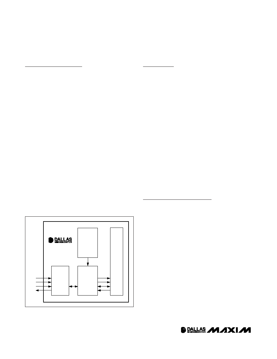
emulator. Figure 5 shows a block diagram of the in-cir-
cuit debugger. The in-circuit debug features include:
Hardware debug engine
Set of registers able to set breakpoints on register,
code, or data accesses
Set of debug service routines stored in the utility
ROM
The embedded hardware debug engine is an indepen-
dent hardware block in the microcontroller. The debug
engine can monitor internal activities and interact with
selected internal registers while the CPU is executing
user code. Collectively, the hardware and software fea-
tures allow two basic modes of in-circuit debugging:
Background mode allows the host to configure and
set up the in-circuit debugger while the CPU contin-
ues to execute the application software at full
speed. Debug mode can be invoked from back-
ground mode.
Debug mode allows the debug engine to take con-
trol of the CPU, providing read/write access to inter-
nal registers and memory, and single-step trace
operation.
Applications Information
Grounds and Bypassing
Careful PC board layout significantly minimizes crosstalk
among the reference input, comparator outputs, and dig-
ital inputs. Keep digital and analog lines separate, and
use ground traces as shields between them where pos-
sible. Separate CMPI and VREF from each other by run-
ning a ground trace between these pins. Bypass VDD
with a capacitor as low as 1F and keep bypass capaci-
tor leads short for best noise rejection.
Capacitor Selection and
Regulator Stability
For general purposes, use a combination of a 10F and
0.1F capacitor on REGOUT. Note that the 0.1F
capacitor is always required on REGOUT and must be
a good quality ceramic with low ESR. The internal regu-
lator is designed to be stable with an output filter
capacitor as low as 4.7F and an ESR as high as 6
Ω.
Larger REGOUT capacitor values and lower ESR pro-
vide better supply-noise rejection and transient
response. Note that some ceramic dielectric materials
(e.g., Z5U and Y5V) exhibit a large temperature coeffi-
cient for both capacitance and ESR, and a larger
REGOUT capacitance may be needed to ensure stabil-
ity at low temperatures.
Applications
The low-power, high-performance RISC architecture of
the MAXQ3210 makes it an excellent fit for many
portable or battery-powered applications that require
cost-effective computing. The analog comparator can
function as an A/D converter when simple analog mea-
surements are necessary, and the high-current I/O pin
can drive a power or status LED. Combined with the
high-output piezoelectric horn/transducer, the micro-
controller can function as both the “brain” and “mouth”
in a wide variety of monitoring applications.
The microcontroller includes an on-chip voltage regula-
tor that allows it to be powered directly off a 9V battery.
A low-battery detector allows the microcontroller to
monitor its own battery condition. The internal voltage
regulator can also drive external 5V circuitry while a 9V
battery drives the system.
This device can also be used as a low-cost analog-to-
digital converter (ADC). The single-slope conversion
method can be easily implemented using the internal
comparator and an internal timer. The basic implemen-
tation of such a converter is illustrated below. One of
the benefits of this approach is the small number of
Microcontroller with Internal Voltage Regulator,
Piezoelectric Horn Driver, and Comparator
22
____________________________________________________________________
TAP
CONTROLLER
CPU
DEBUG
ENGINE
DEBUG
SERVICE
ROUTINES
(UTILITY ROM)
TMS
TCK
TDI
TDO
CONTROL
BREAKPOINT
ADDRESS
DATA
MAXQ3210
Figure 5. In-Circuit Debugger
相关PDF资料 |
PDF描述 |
|---|---|
| MK30DX256ZVLQ10 | IC ARM CORTEX MCU 256KB 144LQFP |
| MC9S12C32MFAE25 | IC MCU 32K FLASH 25MHZ 48-LQFP |
| MC9S12C32MPBE25 | IC MCU 32K FLASH 25MHZ 52-LQFP |
| MC9S12GC96CFAE | IC MCU 96K FLASH 25MHZ 48-LQFP |
| MK20DX256ZVMD10 | IC ARM CORTEX MCU 256KB 144BGA |
相关代理商/技术参数 |
参数描述 |
|---|---|
| MAXQ3210-EJX+ | 功能描述:16位微控制器 - MCU Integrated Circuits (ICs) RoHS:否 制造商:Texas Instruments 核心:RISC 处理器系列:MSP430FR572x 数据总线宽度:16 bit 最大时钟频率:24 MHz 程序存储器大小:8 KB 数据 RAM 大小:1 KB 片上 ADC:Yes 工作电源电压:2 V to 3.6 V 工作温度范围:- 40 C to + 85 C 封装 / 箱体:VQFN-40 安装风格:SMD/SMT |
| MAXQ3210-EMX | 功能描述:16位微控制器 - MCU RoHS:否 制造商:Texas Instruments 核心:RISC 处理器系列:MSP430FR572x 数据总线宽度:16 bit 最大时钟频率:24 MHz 程序存储器大小:8 KB 数据 RAM 大小:1 KB 片上 ADC:Yes 工作电源电压:2 V to 3.6 V 工作温度范围:- 40 C to + 85 C 封装 / 箱体:VQFN-40 安装风格:SMD/SMT |
| MAXQ3210-EMX+ | 功能描述:16位微控制器 - MCU Integrated Circuits (ICs) RoHS:否 制造商:Texas Instruments 核心:RISC 处理器系列:MSP430FR572x 数据总线宽度:16 bit 最大时钟频率:24 MHz 程序存储器大小:8 KB 数据 RAM 大小:1 KB 片上 ADC:Yes 工作电源电压:2 V to 3.6 V 工作温度范围:- 40 C to + 85 C 封装 / 箱体:VQFN-40 安装风格:SMD/SMT |
| MAXQ3210-KIT | 功能描述:开发板和工具包 - 其他处理器 Programmers, Development Systems RoHS:否 制造商:Freescale Semiconductor 产品:Development Systems 工具用于评估:P3041 核心:e500mc 接口类型:I2C, SPI, USB 工作电源电压: |
| MAXQ3212 | 制造商:MAXIM 制造商全称:Maxim Integrated Products 功能描述:Microcontroller with Analog Comparator and LED Driver |
发布紧急采购,3分钟左右您将得到回复。