- 您现在的位置:买卖IC网 > PDF目录1946 > MAXQ7665BATM+T (Maxim Integrated Products)IC MCU-BASED DAS 16BIT 48-TQFN PDF资料下载
参数资料
| 型号: | MAXQ7665BATM+T |
| 厂商: | Maxim Integrated Products |
| 文件页数: | 13/47页 |
| 文件大小: | 0K |
| 描述: | IC MCU-BASED DAS 16BIT 48-TQFN |
| 标准包装: | 2,500 |
| 系列: | MAXQ® |
| 核心处理器: | RISC |
| 芯体尺寸: | 16-位 |
| 速度: | 8MHz |
| 连通性: | CAN,LIN,UART/USART |
| 外围设备: | 欠压检测/复位,POR,PWM,WDT |
| 输入/输出数: | 8 |
| 程序存储器容量: | 64KB(32K x 16) |
| 程序存储器类型: | 闪存 |
| RAM 容量: | 256 x 16 |
| 电压 - 电源 (Vcc/Vdd): | 2.7 V ~ 5.25 V |
| 数据转换器: | A/D 8x12b,D/A 1x12b |
| 振荡器型: | 内部 |
| 工作温度: | -40°C ~ 125°C |
| 封装/外壳: | 48-VFQFN 裸露焊盘 |
| 包装: | 带卷 (TR) |
第1页第2页第3页第4页第5页第6页第7页第8页第9页第10页第11页第12页当前第13页第14页第15页第16页第17页第18页第19页第20页第21页第22页第23页第24页第25页第26页第27页第28页第29页第30页第31页第32页第33页第34页第35页第36页第37页第38页第39页第40页第41页第42页第43页第44页第45页第46页第47页
The MAXQ7665A–MAXQ7665D ADC uses a fully differ-
ential SAR conversion technique and an on-chip T/H
block to convert temperature and voltage signals into a
12-bit digital result. Differential configurations are sup-
ported using an analog input channel MUX that sup-
ports eight differential channels.
The differential analog inputs are selected from the fol-
lowing pairs: AIN0/AIN1, AIN2/AIN3, AIN4/AIN5,
AIN6/AIN7, AIN8/AIN9, AIN10/AIN11, AIN12/AIN13,
and AIN14/AIN15.
Remote temperature-sensor configuration in differential
mode uses analog input channel pairs AIN2/AIN3 and
AIN0/AIN1. In single-ended remote temperature-sensor
configuration, only channels AIN2 and AIN0 are used.
Internal temperature-sensor configuration measures
local die temperature and does not use any analog
input channel.
There are four ways to control the ADC conversion timing:
1) Software register bit control
2) Continuous conversion
3) Internal timers (T0, T1, or T2)
4) External input through pin ADCCNV
Refer to the
MAXQ7665/MAXQ7666 User’s Guide for
more detailed information on the ADC and MUX.
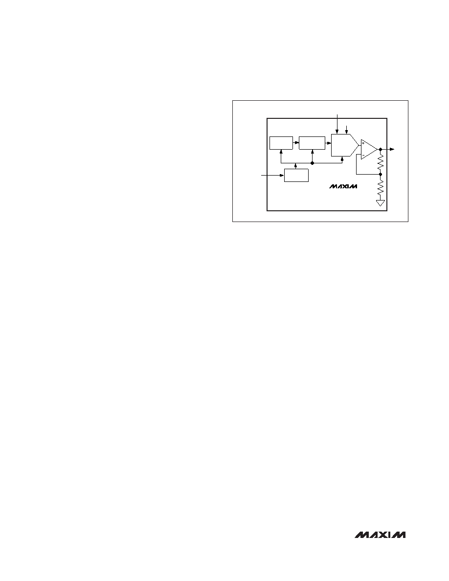
12-Bit Digital-to-Analog Converter (DAC)
The MAXQ7665A–MAXQ7665D contain a 12-bit voltage-
output DAC with its own output buffer. The data path to
the DAC is double buffered and the output register can
be updated using the DACLOAD digital input. Refer to
the
MAXQ7665/MAXQ7666 User’s Guide for detailed
programming information. The DAC also supports a
square-wave-output toggle mode with precise ampli-
tude control for applications that require pulse-ampli-
tude modulation (PAM) and/or pulse-width modulation
(PWM) signals. See Figure 2 for a simplified block dia-
gram of the DAC.
The DAC output buffer is in a voltage follower configu-
ration (gain of 1V/V from REFDAC). The buffer can be
disabled when not in use. When the buffer is disabled,
the output is connected internally to AGND through a
100k resistor. The reference input REFDAC accepts
an input voltage of less than or equal to AVDD for a
maximum output swing of 0V to AVDD.
Temperature Sensor
The C measures temperature by using the on-chip
ADC and a ROM-based tempConv subroutine. Use the
tempConv subroutine to initiate a measurement (refer to
the
MAXQ7665/MAXQ7666 User’s Guide for detailed
information). The device supports conversions of two
external and one on-chip (internal) temperature sen-
sors. The external temperature sensor is typically a
diode-connected small-signal transistor, connected
between two analog inputs (differential) or one analog
input and AGND (single-ended). Figures 3 and 4 illus-
trate these two configurations.
MAXQ7665A–MAXQ7665D
16-Bit RISC Microcontroller-Based
Smart Data-Acquisition Systems
20
_______________________________________________________________________________________
REFDAC
DACE
R
DAC INPUT
REGISTER
P0.5/DACLOAD
DACOUT
DAC OUTPUT
REGISTER
12-BIT DAC
DAC LOAD
CONTROL
MAXQ7665A–MAXQ7665D
Figure 2. Simplified DAC Diagram
相关PDF资料 |
PDF描述 |
|---|---|
| MAXQ7667AACM/V+T | IC MCU-BASED DAS 16BIT 48-LQFP |
| MAXQ7670AATL/V+ | IC MCU W/12BIT ADC 40TQFN-EP |
| MAXQ7670ATL+ | IC MCU W/10BIT ADC 40TQFN-EP |
| MB86R01PB-GSE1 | IC SOC GRAPHIC CONTRLR 484BGA |
| MB90F387PMT-GSE1 | IC MCU FLASH 64K ROM 48LQFP |
相关代理商/技术参数 |
参数描述 |
|---|---|
| MAXQ7665C | 制造商:MAXIM 制造商全称:Maxim Integrated Products 功能描述:16-Bit RISC Microcontroller-Based Smart Data-Acquisition Systems |
| MAXQ7665CATM+ | 制造商:MAXIM 制造商全称:Maxim Integrated Products 功能描述:16-Bit RISC Microcontroller-Based Smart Data-Acquisition Systems |
| MAXQ7665D | 制造商:MAXIM 制造商全称:Maxim Integrated Products 功能描述:16-Bit RISC Microcontroller-Based Smart Data-Acquisition Systems |
| MAXQ7665DATM+ | 制造商:MAXIM 制造商全称:Maxim Integrated Products 功能描述:16-Bit RISC Microcontroller-Based Smart Data-Acquisition Systems |
| MAXQ7665EVKIT# | 功能描述:开发板和工具包 - 其他处理器 Programmers, Development Systems RoHS:否 制造商:Freescale Semiconductor 产品:Development Systems 工具用于评估:P3041 核心:e500mc 接口类型:I2C, SPI, USB 工作电源电压: |
发布紧急采购,3分钟左右您将得到回复。