- 您现在的位置:买卖IC网 > PDF目录377893 > MB86291A (Fujitsu Limited) Graphics Display Controller PDF资料下载
参数资料
| 型号: | MB86291A |
| 厂商: | Fujitsu Limited |
| 英文描述: | Graphics Display Controller |
| 中文描述: | 图形显示控制器 |
| 文件页数: | 6/25页 |
| 文件大小: | 243K |
| 代理商: | MB86291A |
MB86291A
6
Notes :
The host interface transfers data signals at a fixed width of 32 bits.
There are 23 lines for address signals handled in double words (
=
32 bits) and 32 Mbytes of address
space.
The external bus can be used at an operating frequency of 100 MHz maximum.
The RDY signal at the low level sets the ready state in the SH4 or V832 mode; the signal at the low level
sets the wait state in the SH3 mode. Note that the RDY signal is a tristate output.
The host interface supports DMA transfer using an external DMA controller.
The host interface generates a host processor interrupt signal.
The RESET pin requires low level input of at least 300
μ
s after setting “S” (PLL reset signal) to high level.
Fix the TEST signal at high level.
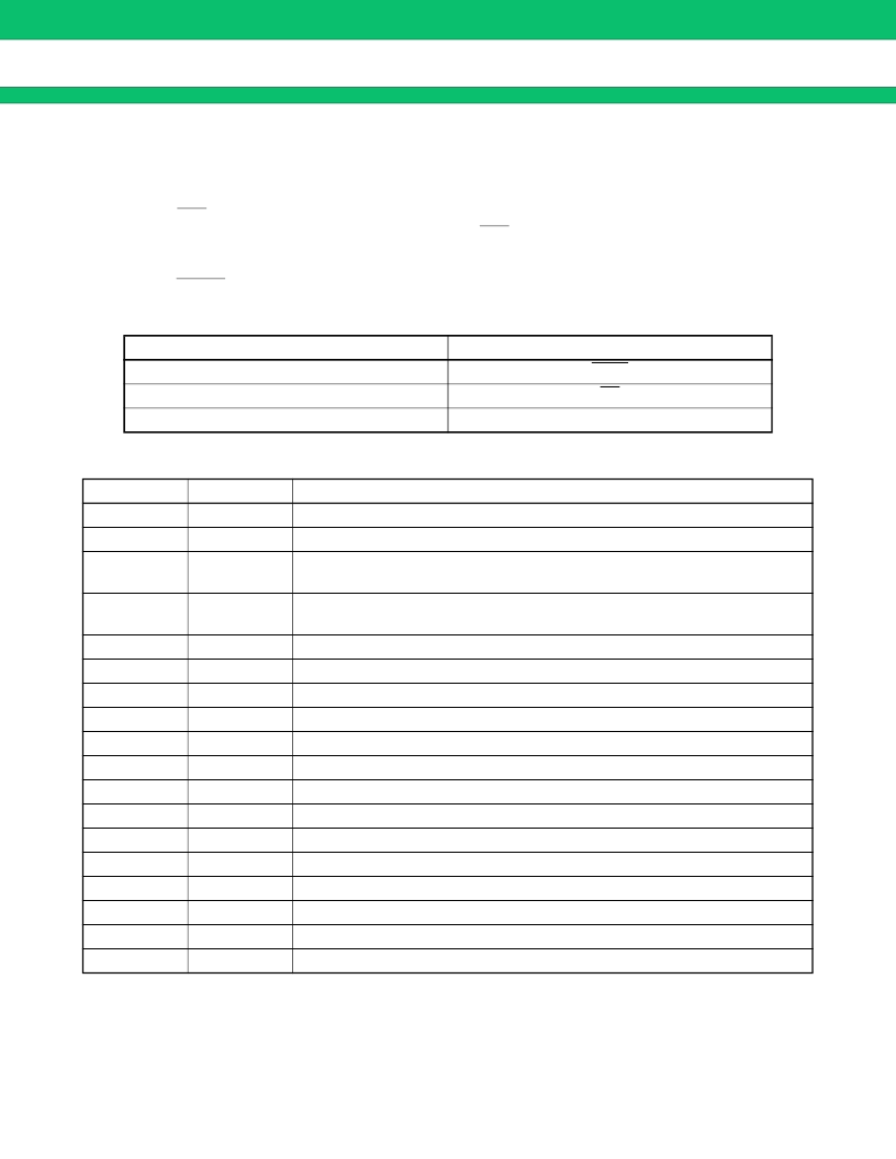
In the V832 mode, connect the following pins as specified :
SCARLET Pin Name
A24
DTACK
DRACK
Vide Output Interface
Pin Name
DCLKO
DCLKI
Notes :
The video output interface contains an 8-bit D/A converter to output analog RGB signals. Also, the
eight-bit RGB digital output pins can connect an external digital video encoder.
Using an additional external circuit, the video output interface can generate composite video signals.
The video output interface can provide display synchronized with external video. The mode for
synchronization with the DCLKI signal can be selected as well as the mode for synchronization with a set
dot clock as for normal display.
V832 Signal Name
MWR
TC
DMAAK
Input/output
Output
Input
Function
Display dot clock signal output
Dot clock signal input
Horizontal sync signal output
Horizontal sync signal input in external synchronization mode
Vertical sync signal output
Vertical sync signal input in external synchronization mode
Composite sync signal output
Even/odd-number field identification input
Graphics/video select signal
Digital video (R) signal output
Digital video (G) signal output
Digital video (B) signal output
Analog output Analog video (R) signal output
Analog output Analog video (G) signal output
Analog output Analog video (B) signal output
Analog
Reference voltage input pin
Analog
R-signal compensation pin
Analog
G-signal compensation pin
Analog
B-signal compensation pin
Analog
Reference current setting pin
HSYNC
Input/output
VSYNC
Input/output
CSYNC
EO
GV
R0-R7
G0-G7
B0-B7
AOUTR
AOUTG
AOUTB
VREF
ACOMPR
ACOMPG
ACOMPB
VRO
Output
Input
Output
Output
Output
Output
相关PDF资料 |
PDF描述 |
|---|---|
| MB86291APFVS | Graphics Display Controller |
| MB86292 | Graphics Display Controller |
| MB86292PFFS-G-BND | Graphics Display Controller |
| MB86293 | Grraphiics Conttrrollllerr Speciiffiicattiions |
| MB86294 | Grraphiics Controller specifications |
相关代理商/技术参数 |
参数描述 |
|---|---|
| MB86291APFVS | 制造商:FUJITSU 制造商全称:Fujitsu Component Limited. 功能描述:Graphics Display Controller |
| MB86291APFVS-G-BND-DLE1 | 制造商:FUJITSU 功能描述:CONTROLLER GRAPHDISPLAY QFP208 |
| MB86291APFVSGBNDL | 制造商:Fujitsu 功能描述: |
| MB86291APVSR-G-BND-DLE1 | 制造商:FUJITSU 功能描述: |
| MB86291ASPVSR-G-BND-DLE1 | 制造商:FUJITSU 功能描述: |
发布紧急采购,3分钟左右您将得到回复。