- 您现在的位置:买卖IC网 > PDF目录81409 > MBR3035CT-E3 (VISHAY SEMICONDUCTORS) 15 A, 35 V, SILICON, RECTIFIER DIODE, TO-220AB PDF资料下载
参数资料
| 型号: | MBR3035CT-E3 |
| 厂商: | VISHAY SEMICONDUCTORS |
| 元件分类: | 整流器 |
| 英文描述: | 15 A, 35 V, SILICON, RECTIFIER DIODE, TO-220AB |
| 封装: | PLASTIC PACKAGE-3 |
| 文件页数: | 1/3页 |
| 文件大小: | 57K |
| 代理商: | MBR3035CT-E3 |
MBR3045CT, MBRF3045CT & MBRB3045CT Series
Vishay Semiconductors
formerly General Semiconductor
New Product
Dual Schottky Rectifiers
Reverse Voltage 30 to 45V
Forward Current 30A
0.08
(2.032)
0.24
(6.096)
0.42
(10.66)
0.63
(17.02)
0.12
(3.05)
0.33
(8.38)
Mounting Pad Layout TO-263AB
0.380 (9.65)
0.411 (10.45)
0.320 (8.13)
0.360 (9.14)
0.591 (15.00)
0.624 (15.85)
1
2
0.245 (6.22)
MIN
K
0.160 (4.06)
0.190 (4.83)
0.045 (1.14)
0.055 (1.40)
0.014 (0.36)
0.021 (0.53)
0.110 (2.79)
0.140 (3.56)
0.090 (2.29)
0.110 (2.79)
0.047 (1.19)
0.055 (1.40)
PIN 1
PIN 2
K - HEATSINK
0-0.01 (0-0.254)
0.027 (0.686)
0.037 (0.940)
0.105 (2.67)
0.095 (2.41)
0.205 (5.20)
0.195 (4.95)
1
3
PIN
2
0.060 (1.52)
0.405 (10.27)
0.383 (9.72)
0.191 (4.85)
0.171 (4.35)
0.600 (15.5)
0.580 (14.5)
0.560 (14.22)
0.530 (13.46)
0.037 (0.94)
0.027 (0.69)
0.140 (3.56)
0.130 (3.30)
0.350 (8.89)
0.330 (8.38)
0.188 (4.77)
0.172 (4.36)
0.110 (2.80)
0.100 (2.54)
0.131 (3.39)
0.122 (3.08)
0.110 (2.80)
0.100 (2.54)
0.022 (0.55)
0.014 (0.36)
DIA.
0.676 (17.2)
0.646 (16.4)
0.205 (5.20)
0.195 (4.95)
0.105 (2.67)
0.095 (2.41)
PIN 2
PIN 1
PIN 3
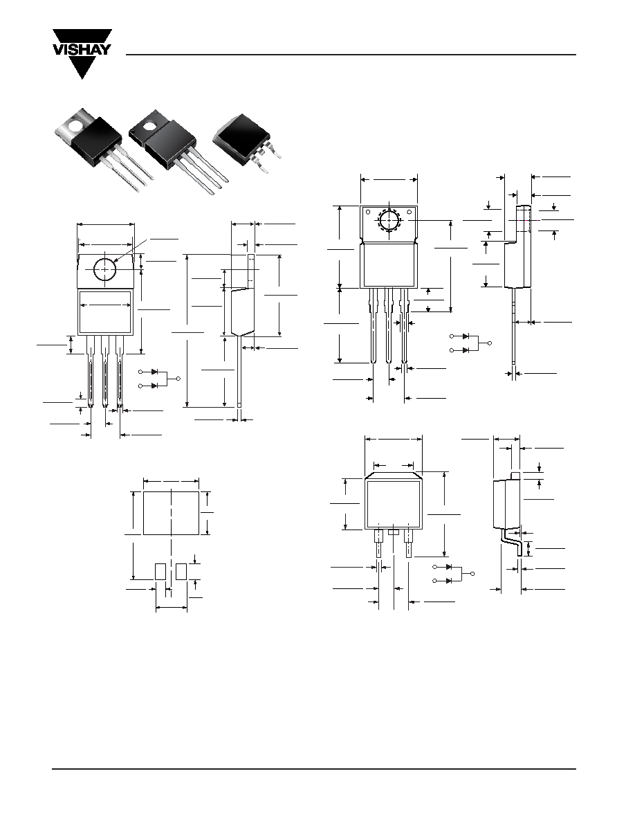
ITO-220AB (MBRF3035CT, MBRF3045CT)
TO-220AB (MBR3035CT, MBR3045CT)
Dimensions in inches
and (millimeters)
TO-263AB (MBRB3035CT, MBRB3045CT)
12
3
PIN
0.185 (4.70)
0.175 (4.44)
0.055 (1.39)
0.045 (1.14)
0.145 (3.68)
0.135 (3.43)
0.350 (8.89)
0.330 (8.38)
0.560 (14.22)
0.530 (13.46)
0.022 (0.56)
0.014 (0.36)
0.110 (2.79)
0.100 (2.54)
0.603 (15.32)
0.573 (14.55)
CASE
1.148 (29.16)
1.118 (28.40)
PIN 2
0.154 (3.91)
0.148 (3.74)
0.113 (2.87)
0.103 (2.62)
0.160 (4.06)
0.140 (3.56)
0.410 (10.41)
0.390 (9.91)
0.635 (16.13)
0.625 (15.87)
0.415 (10.54) MAX.
0.370 (9.40)
0.360 (9.14)
PIN 1
PIN 3
0.028 (0.70)
0.104 (2.65)
0.096 (2.45)
0.035 (0.90)
0.205 (5.20)
0.195 (4.95)
0.105 (2.67)
0.095 (2.41)
Features
Plastic package has Underwriters Laboratory
Flammability Classification 94V-0
Dual rectifier construction, positive center tap
Metal silicon junction, majority carrier conduction
Low power loss, high efficiency
Guardring for overvoltage protection
For use in low voltage, high frequency inverters, free
wheeling, and polarity protection applications
Mechanical Data
Case: JEDEC TO-220AB, ITO-220AB, TO-263AB
molded plastic body
Terminals: Plated leads, solderable per
MIL-STD-750, Method 2026
High temperature soldering guaranteed:
250°C/10 seconds, 0.25" (6.35mm) from case (TO-220AB,
ITO-220AB) at terminals (TO-236AB)
Polarity: As marked Mounting Position: Any
Mounting Torque: 10 in-lbs maximum
Weight: 0.08 oz., 2.24 g
Document Number 88677
www.vishay.com
02-Oct-02
1
相关PDF资料 |
PDF描述 |
|---|---|
| MBRB10100-E3 | 10 A, 100 V, SILICON, RECTIFIER DIODE, TO-263AB |
| MBRB1035/45-E3 | 10 A, 35 V, SILICON, RECTIFIER DIODE, TO-263AB |
| MBRB1060/45-E3 | 10 A, 60 V, SILICON, RECTIFIER DIODE, TO-263AB |
| MBRB10H100/31-E3 | 10 A, 100 V, SILICON, RECTIFIER DIODE, TO-263AB |
| MBRB10H90/45-E3 | 10 A, 90 V, SILICON, RECTIFIER DIODE, TO-263AB |
相关代理商/技术参数 |
参数描述 |
|---|---|
| MBR3035CT-E3/45 | 功能描述:肖特基二极管与整流器 35 Volt 30A Dual Common-Cathode RoHS:否 制造商:Skyworks Solutions, Inc. 产品:Schottky Diodes 峰值反向电压:2 V 正向连续电流:50 mA 最大浪涌电流: 配置:Crossover Quad 恢复时间: 正向电压下降:370 mV 最大反向漏泄电流: 最大功率耗散:75 mW 工作温度范围:- 65 C to + 150 C 安装风格:SMD/SMT 封装 / 箱体:SOT-143 封装:Reel |
| MBR3035CTP | 制造商:VISHAY 制造商全称:Vishay Siliconix 功能描述:Schottky Rectifier, 2 x 15 A |
| MBR3035CTPBF | 制造商:VISHAY 制造商全称:Vishay Siliconix 功能描述:Schottky Rectifier, 2 x 15 A |
| MBR3035CTTRLP | 制造商:VISHAY 制造商全称:Vishay Siliconix 功能描述:Schottky Rectifier, 2 x 15 A |
| MBR3035CTTRLPBF | 制造商:VISHAY 制造商全称:Vishay Siliconix 功能描述:Schottky Rectifier, 2 x 15 A |
发布紧急采购,3分钟左右您将得到回复。