- 您现在的位置:买卖IC网 > PDF目录378654 > MC10136FN (MOTOROLA INC) Universal Hexadecimal Counter PDF资料下载
参数资料
| 型号: | MC10136FN |
| 厂商: | MOTOROLA INC |
| 元件分类: | 通用总线功能 |
| 英文描述: | Universal Hexadecimal Counter |
| 中文描述: | 10K SERIES, SYN POSITIVE EDGE TRIGGERED 4-BIT BIDIRECTIONAL BINARY COUNTER, PQCC20 |
| 封装: | PLASTIC, LCC-20 |
| 文件页数: | 4/8页 |
| 文件大小: | 150K |
| 代理商: | MC10136FN |
MC10136
MOTOROLA
MECL Data
DL122 — Rev 6
3–30
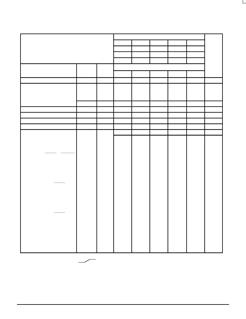
ELECTRICAL CHARACTERISTICS
(continued)
TEST VOLTAGE VALUES
(Volts)
@ Test Temperature
VIHmax
–0.890
VILmin
–1.890
VIHAmin
–1.205
VILAmax
–1.500
VEE
–5.2
–30
°
C
+25
°
C
–0.810
–1.850
–1.105
–1.475
–5.2
+85
°
C
–0.700
–1.825
–1.035
–1.440
–5.2
Pin
Under
Test
TEST VOLTAGE APPLIED TO PINS LISTED BELOW
(VCC)
Gnd
Characteristic
Symbol
VIHmax
VILmin
VIHAmin
VILAmax
VEE
8
Power Supply Drain Current
IE
IinH
8
1, 16
Input Current
5,6,11,12
7
9,10
13
5,6,11,12
7
9,10
13
8
8
8
8
1, 16
1, 16
1, 16
1, 16
IinL
VOH
VOL
VOHA
VOLA
All
Note 1.
8
1, 16
Output Voltage
Logic 1
14
(
2.
)
12
7, 9
8
1, 16
Output Voltage
Logic 0
14
(
2.
)
7, 9
8
1, 16
Threshold Voltage
Logic 1
14
(
2.
)
7, 9
12
8
1, 16
Threshold Voltage
Logic 0
14
(
2.
)
7, 9
12
8
1, 16
Switching Times
(50
Load)
+1.11V
+0.31V
Pulse In
Pulse Out
–3.2 V
+2.0 V
Propagation Delay
Clock Input
t13+14+
t13+14–
t13+4+
t13+4–
t10–4–
t10+4+
t12+13+
t12–13+
t9+13+
t7+13+
t10–13+
t10+13+
t13+12+
t13+12–
t13+9+
t13+7+
t13+10–
t13+10+
fcountup
fcountdown
t4+
t14+
t4–
t14–
14
14
4
4
12
7
7
13
13
13
13
14
14
4
4
8
8
8
8
1, 16
1, 16
1, 16
1, 16
Carry In to Carry Out
4
(3.)
4
7
7
13
13
10
10
4
4
8
8
1, 16
1, 16
Setup Time
Data Inputs
14
14
7, 9
7, 9
12, 13
12, 13
14
14
8
8
1, 16
1, 16
Select Inputs
14
14
9, 13
7, 13
14
14
8
8
1, 16
1, 16
Carry In Inputs
14
14
7
7
9
9
10, 13
10, 13
14
14
8
8
1, 16
1, 16
Hold Time
Data Inputs
14
14
7, 9
7, 9
12, 13
12, 13
14
14
8
8
1, 16
1, 16
Select Inputs
14
14
9, 13
7, 13
14
14
8
8
1, 16
1, 16
Carry In Inputs
14
14
7
7
9
10, 13
10, 13
14
14
8
8
1, 16
1, 16
Counting Frequency
14
14
7
9
13
13
14
14
8
8
1, 16
1, 16
Rise Time
(20 to 80%)
4
14
7
7
13
13
4
14
8
8
1, 16
1, 16
Fall Time
(20 to 80%)
4
14
7
7
13
13
4
14
8
8
1, 16
1, 16
1. Individually test each input; apply VILmin to pin under test.
2. Measure output after clock pulse
VIH
VIL
appears at clock input (Pin 13).
3. Before test set all Q outputs to a logic high.
4. To preserve reliable performance, the MC10136 (plastic packaged device only) is to be operated in ambient temperatures above 70
°
C only
when 500lfpm blown air or equivalent heat sinking is provided.
Each MECL 10,000 series circuit has been designed to meet the dc specifications shown in the test table, after thermal equilibrium has been
established. The circuit is in a test socket or mounted on a printed circuit board and transverse air flow greater than 500 linear fpm is maintained.
Outputs are terminated through a 50-ohm resistor to –2.0 volts. Test procedures are shown for only one gate. The other gates are tested in the
same manner.
相关PDF资料 |
PDF描述 |
|---|---|
| MC10136 | Universal Hexadecimal Counter |
| MC10136L | 9-Bit Odd/Even Parity Generators/Checkers 14-CDIP -55 to 125 |
| MC10136P | Universal Hexadecimal Counter |
| MC10137L | Replaced by CD54HCT191 : Synchronous Up/Down Counters With Down/Up Mode Control 16-CDIP -55 to 125 |
| MC10137 | Universal Decade Counter |
相关代理商/技术参数 |
参数描述 |
|---|---|
| MC10136FN WAF | 制造商:ON Semiconductor 功能描述: |
| MC10136FNR2 | 制造商:Motorola Inc 功能描述: |
| MC10136L | 制造商:ON Semiconductor 功能描述:Counter Single 4-Bit Hexadecimal UP/Down 16-Pin CDIP Rail 制造商:Rochester Electronics LLC 功能描述:- Bulk |
| MC10136P | 制造商:ON Semiconductor 功能描述:Counter Single 4-Bit Hexadecimal UP/Down 16-Pin PDIP Rail 制造商:Rochester Electronics LLC 功能描述:- Bulk |
| MC10137L | 制造商:Motorola Inc 功能描述: |
发布紧急采购,3分钟左右您将得到回复。