- 您现在的位置:买卖IC网 > PDF目录10926 > MC145483DT (Freescale Semiconductor)IC PCM COD-FILT 3V 13BIT 20TSSOP PDF资料下载
参数资料
| 型号: | MC145483DT |
| 厂商: | Freescale Semiconductor |
| 文件页数: | 21/24页 |
| 文件大小: | 0K |
| 描述: | IC PCM COD-FILT 3V 13BIT 20TSSOP |
| 标准包装: | 75 |
| 类型: | PCM 编解码器/滤波器 |
| 数据接口: | PCM 音频接口 |
| 分辨率(位): | 13 b |
| ADC / DAC 数量: | 1 / 1 |
| 三角积分调变: | 无 |
| 电压 - 电源,数字: | 2.7 V ~ 5.25 V |
| 工作温度: | -40°C ~ 85°C |
| 安装类型: | 表面贴装 |
| 封装/外壳: | 20-TSSOP(0.173",4.40mm 宽) |
| 供应商设备封装: | 20-TSSOP |
| 包装: | 管件 |
FUNCTIONAL DESCRIPTION
ANALOG INTERFACE AND SIGNAL PATH
The transmit portion of this device includes a low–noise,
three–terminal op amp capable of driving a 2 k
load. This
op amp has inputs of TI+ (Pin 19) and TI– (Pin 18) and its
output is TG (Pin 17). This op amp is intended to be confi-
gured in an inverting gain circuit. The analog signal may be
applied directly to the TG pin if this transmit op amp is inde-
pendently powered down by connecting the TI+ input to the
VDD power supply. The TG pin becomes high impedance
when the transmit op amp is powered down. The TG pin is
internally connected to a 3–pole anti–aliasing pre–filter. This
pre–filter incorporates a 2–pole Butterworth active low–pass
filter, followed by a single passive pole. This pre–filter is fol-
lowed by a single–ended to differential converter that is
clocked at 512 kHz. All subsequent analog processing uti-
lizes fully–differential circuitry. The next section is a fully–dif-
ferential, 5–pole switched–capacitor low–pass filter with a
3.4 kHz frequency cutoff. After this filter is a 3–pole
switched–capacitor high–pass filter having a cutoff fre-
quency of about 200 Hz. This high–pass stage has a trans-
mission zero at dc that eliminates any dc coming from the
analog input or from accumulated op amp offsets in the pre-
ceding filter stages. The high–pass filter may be bypassed or
removed from the signal path by the HB pin. When the high–
pass filter is bypassed, the frequency response extends
down to include dc. The last stage of the high–pass filter is
an autozeroed sample and hold amplifier.
One bandgap voltage reference generator and digital–to–
analog converter (DAC) are shared by the transmit and re-
ceive sections. The autozeroed, switched–capacitor
bandgap reference generates precise positive and negative
reference voltages that are virtually independent of tempera-
ture and power supply voltage. A capacitor array (CDAC) is
combined with a resistor string (RDAC) to implement the
13–bit linear DAC structure. The encode process uses the
DAC, the voltage reference, and a frame–by–frame auto-
zeroed comparator to implement a successive approxima-
tion conversion algorithm. All of the analog circuitry involved
in the data conversion (the voltage reference, RDAC, CDAC,
and comparator) are implemented with a differential architec-
ture.
The receive section includes the DAC described above, a
sample and hold amplifier, a 5–pole, 3400 Hz switched ca-
pacitor low–pass filter with sinX/X correction, and a 2–pole
active smoothing filter to reduce the spectral components of
the switched capacitor filter. The output of the smoothing fil-
ter is buffered by an amplifier, which is output at the RO– pin.
This output is capable of driving a 2 k
load to the VAG pin.
The MC145483 also has a pair of power amplifiers that are
connected in a push–pull configuration. The PI pin is the in-
verting input to the PO– power amplifier. The non–inverting
input is internally tied to the VAG pin. This allows this amplifier
to be used in an inverting gain circuit with two external resis-
tors. The PO+ amplifier has a gain of minus one, and is in-
ternally connected to the PO– output. This complete power
amplifier circuit is a differential (push–pull) amplifier with ad-
justable gain. The power amplifier may be powered down in-
dependently of the rest of the chip by connecting the PI pin to
VDD.
The calibration level for both ADC and DAC of this 13–bit
linear PCM Codec–Filter is referenced to Mu–Law with the
same bit voltage weighting about the zero crossing. This re-
sults in the 0 dBm0 calibration level being 3.20 dB below the
peak sinusoidal level before clipping. Based on the reference
voltage of 0.886 V, the calibration level is 0.436 Vrms or
– 5 dBm at 600
.
The MC145483 has the ability to attenuate the receive
analog output when used in the receive gain adjust mode.
This mode is accessed by applying a logic high to the
BCLKR pin while the rest of the clock pins are clocked nor-
mally. This allows three additional bits that will be used to
control the gain of the analog output to be clocked into the
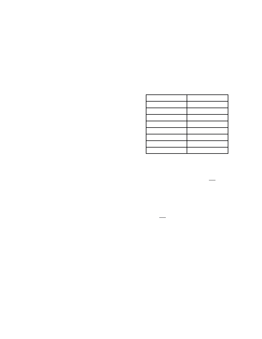
DR pin following the 13 bits of voice data. Table 1 shows the
attenuation values and the corresponding digital codes.
Table 1. Receive Gain Adjust Mode
Coefficients and Attenuation Weightings
Coefficient
Attenuation in dB
000
0
001
– 3
010
– 6
011
– 9
100
– 12
101
– 15
110
– 18
111
– 21
POWER–DOWN
There are two methods of putting this device into a low
power consumption mode, which makes the device nonfunc-
tional and consumes virtually no power. PDI is the power–
down input pin which, when taken low, powers down the
device. Another way to power the device down is to hold both
the FST and FSR pins low while the BCLKT and MCLK pins
are clocked. When the chip is powered down, the VAG, TG,
RO–, PO+, PO–, and DT outputs are high impedance and
the VAG Ref pin is pulled to the VDD power supply with a non–
linear, high–impedance circuit. To return the chip to the pow-
er–up state, PDI must be high and the FST frame sync pulse
must be present while the BCLKT and MCLK pins are
clocked. The DT output will remain in a high–impedance
state for at least two 8 kHz FST pulses after power–up.
MASTER CLOCK
Since this codec–filter design has a single DAC architec-
ture, the MCLK pin is used as the master clock for all analog
signal processing including analog–to–digital conversion,
digital–to–analog conversion, and for transmit and receive fil-
tering functions of this device. The clock frequency applied to
the MCLK pin may be 256 kHz, 512 kHz, 1.536 MHz,
1.544 MHz, 2.048 MHz, 2.56 MHz, or 4.096 MHz. This de-
vice has a prescaler that automatically determines the proper
divide ratio to use for the MCLK input, which achieves the re-
quired 256 kHz internal sequencing clock. The clocking re-
quirements of the MCLK input are independent of the PCM
data transfer mode (i.e., Long Frame Sync, Short Frame
Sync, whether the device is used in the synchronous modes
or not).
F
re
e
sc
a
le
S
e
m
ic
o
n
d
u
c
to
r,
I
Freescale Semiconductor, Inc.
For More Information On This Product,
Go to: www.freescale.com
n
c
..
.
相关PDF资料 |
PDF描述 |
|---|---|
| MC145481DT | IC PCM CODEC-FILTER 3V 20-TSSOP |
| MPC5566MZP144 | IC MCU 32BIT 3MB FLASH 416PBGA |
| MCIMX515CJM6C | MULTIMEDIA PROC 529-LFBGA |
| SPC5566MVR144 | MCU 3MB FLASH 144MHZ 416-PBGA |
| JBXFD1G06MCSDSR | CONN PLUG 6POS STR CABLE CRIMP |
相关代理商/技术参数 |
参数描述 |
|---|---|
| MC145483DW | 功能描述:IC CODEC-FILTER PCM 3V 20-SOIC RoHS:否 类别:集成电路 (IC) >> 接口 - 编解码器 系列:- 标准包装:2,500 系列:- 类型:立体声音频 数据接口:串行 分辨率(位):18 b ADC / DAC 数量:2 / 2 三角积分调变:是 S/N 比,标准 ADC / DAC (db):81.5 / 88 动态范围,标准 ADC / DAC (db):82 / 87.5 电压 - 电源,模拟:2.6 V ~ 3.3 V 电压 - 电源,数字:1.7 V ~ 3.3 V 工作温度:-40°C ~ 85°C 安装类型:表面贴装 封装/外壳:48-WFQFN 裸露焊盘 供应商设备封装:48-TQFN-EP(7x7) 包装:带卷 (TR) |
| MC145483DWR2 | 功能描述:IC CODEC-FILTER PCM 3V 20-SOIC RoHS:否 类别:集成电路 (IC) >> 接口 - 编解码器 系列:- 标准包装:2,500 系列:- 类型:立体声音频 数据接口:串行 分辨率(位):18 b ADC / DAC 数量:2 / 2 三角积分调变:是 S/N 比,标准 ADC / DAC (db):81.5 / 88 动态范围,标准 ADC / DAC (db):82 / 87.5 电压 - 电源,模拟:2.6 V ~ 3.3 V 电压 - 电源,数字:1.7 V ~ 3.3 V 工作温度:-40°C ~ 85°C 安装类型:表面贴装 封装/外壳:48-WFQFN 裸露焊盘 供应商设备封装:48-TQFN-EP(7x7) 包装:带卷 (TR) |
| MC145483EG | 功能描述:IC CODEC-FILTER PCM 3V 20-SOIC RoHS:是 类别:集成电路 (IC) >> 接口 - 编解码器 系列:- 标准包装:2,500 系列:- 类型:立体声音频 数据接口:串行 分辨率(位):18 b ADC / DAC 数量:2 / 2 三角积分调变:是 S/N 比,标准 ADC / DAC (db):81.5 / 88 动态范围,标准 ADC / DAC (db):82 / 87.5 电压 - 电源,模拟:2.6 V ~ 3.3 V 电压 - 电源,数字:1.7 V ~ 3.3 V 工作温度:-40°C ~ 85°C 安装类型:表面贴装 封装/外壳:48-WFQFN 裸露焊盘 供应商设备封装:48-TQFN-EP(7x7) 包装:带卷 (TR) |
| MC145483EGR2 | 功能描述:IC CODEC-FILTER PCM 3V 20-SOIC RoHS:是 类别:集成电路 (IC) >> 接口 - 编解码器 系列:- 标准包装:2,500 系列:- 类型:立体声音频 数据接口:串行 分辨率(位):18 b ADC / DAC 数量:2 / 2 三角积分调变:是 S/N 比,标准 ADC / DAC (db):81.5 / 88 动态范围,标准 ADC / DAC (db):82 / 87.5 电压 - 电源,模拟:2.6 V ~ 3.3 V 电压 - 电源,数字:1.7 V ~ 3.3 V 工作温度:-40°C ~ 85°C 安装类型:表面贴装 封装/外壳:48-WFQFN 裸露焊盘 供应商设备封装:48-TQFN-EP(7x7) 包装:带卷 (TR) |
| MC145483EJ | 功能描述:IC CODEC-FI 13BIT 3V 20-TSSOP RoHS:是 类别:集成电路 (IC) >> 接口 - 编解码器 系列:- 标准包装:2,500 系列:- 类型:立体声音频 数据接口:串行 分辨率(位):18 b ADC / DAC 数量:2 / 2 三角积分调变:是 S/N 比,标准 ADC / DAC (db):81.5 / 88 动态范围,标准 ADC / DAC (db):82 / 87.5 电压 - 电源,模拟:2.6 V ~ 3.3 V 电压 - 电源,数字:1.7 V ~ 3.3 V 工作温度:-40°C ~ 85°C 安装类型:表面贴装 封装/外壳:48-WFQFN 裸露焊盘 供应商设备封装:48-TQFN-EP(7x7) 包装:带卷 (TR) |
发布紧急采购,3分钟左右您将得到回复。