- 您现在的位置:买卖IC网 > PDF目录11784 > MC33972ATEW (Freescale Semiconductor)IC SWITCH DETECT SPI 32-SOIC PDF资料下载
参数资料
| 型号: | MC33972ATEW |
| 厂商: | Freescale Semiconductor |
| 文件页数: | 16/32页 |
| 文件大小: | 0K |
| 描述: | IC SWITCH DETECT SPI 32-SOIC |
| 标准包装: | 42 |
| 应用: | 开关监控 |
| 接口: | SPI 串行 |
| 电源电压: | 3.1 V ~ 5.25 V |
| 封装/外壳: | 32-BSSOP 裸露焊盘 |
| 供应商设备封装: | 32-SOIC |
| 包装: | 管件 |
| 安装类型: | 表面贴装 |
第1页第2页第3页第4页第5页第6页第7页第8页第9页第10页第11页第12页第13页第14页第15页当前第16页第17页第18页第19页第20页第21页第22页第23页第24页第25页第26页第27页第28页第29页第30页第31页第32页
Analog Integrated Circuit Device Data
Freescale Semiconductor
23
33972
TYPICAL APPLICATIONS
INTRODUCTION
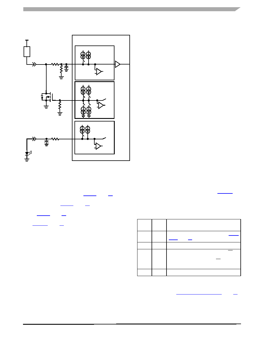
Figure 15. MOSFET or LED Driver Output
The sequence of commands (from Normal mode with
inputs tri-state) required to set up the device to drive a
MOSFET are as follows:
wetting current timer enable command –Disable SPn
metallic command –Set SPn to 16 or 2.0 mA gate drive
current (refer to Table 8, page 15).
settings command –Set SPn as switch-to-battery (refer
tri-state command –Disable tri-state for SPn (refer to
After the tri-state command has been sent (tri-state
disable), the MOSFET gate will be pulled to ground. From this
point forward the MOSFET may be turned on and off by
sending the settings command:
settings command –SPn as switch-to-ground
(MOSFET ON).
settings command –SPn as switch-to-battery
(MOSFET OFF).
Monitoring of the MOSFET drain in the OFF state provides
open load detection. This is done by using an SGn input
comparator. With the SGn input in tri-state, the load will pull
up the SGn input to battery. With open load the SGn pin is
pulled down to ground through an external resistor. The open
load is indicated by a logic [1] in the SO data bit.
The analog command may be used to monitor the drain
voltage in the MOSFET ON state. By sourcing 2.0 mA of
current to the 1.5 k
Ω resistor, the analog voltage on the SGn
pin will be approximately:
As the voltage on the drain of the MOSFET increases, so
does the voltage on the SGn pin. With the SGn pin selected
as analog, the MCU may perform the A/D conversion.
Using this method for controlling unclamped inductive
loads is not recommended. Inductive flyback voltages greater
than VPWR may damage the IC.
The SP0:SP7 pins of this device may also be used to send
signals from one module to another. Operation is similar to
the gate control of a MOSFET.
For LED applications a resistor in series with the LED is
recommended but not required. The switch-to-ground
inputs are recommended for LED application. To drive
the LED use the following commands:
wetting current timer enable command –Disable SGn
wetting current timer.
metallic command –Set SGn to 16 mA.
From this point forward the LED may be turned on and off
using the tri-state command:
tri-state command –Disable tri-state for SGn (LED ON).
tri-state command –Enable tri-state for SGn (LED
OFF).
These parameters are easily programmed via SPI
commands in Normal mode.
MULTIPLE 33972 DEVICES IN A MODULE SYSTEM
Connecting power to the 33972 and the MCU for Sleep
mode operation may be done in several ways. Table 21
shows several system configurations for power between the
MCU and the 33972 and their specific requirements for
functionality.
Multiple 33972 devices may be used in a module system.
SPI control may be done in parallel or serial. However when
parallel mode is used, each device is addressed
independently (refer to MCU Interface Description, page 13).
Therefore when sending the sleep command, one device will
enter sleep before the other. For multiple devices in a system,
it is recommended that the devices are controlled in serial (S0
SP0
SG0
SG13
16
2.0
4.0V Ref
+
-
Comparator
To SPI
VPWR
SG0
1.5k
Ω
LO
A
D
VBAT
AMUX
100k
Ω
mA
VPWR
+
-
Comparator
To SPI
4.0V
Ref
2.0
2.0mA
16
mA
16
mA
VPWR
SG0
16
2.0
VPWR
mA
VPWR
+
Comparator
To SPI
4.0V Ref
SG13
-
mA
Table 21. Sleep Mode Power Supply
MCU
VDD
33972
VDD
Comments
5.0 V
All wake-up conditions apply. (Refer to Sleep
5.0 V
0 V
SPI wake-up is not possible.
0 V
5.0 V
Sleep mode not possible. Current from CS pull-
up will flow through MCU to VDD that has been
switched off. Negative edge of CS will put
33972 in Normal mode.
0 V
SPI wake-up is not possible.
VSGn = ISGn x 1.5kΩ + VDS
相关PDF资料 |
PDF描述 |
|---|---|
| VI-J5P-IW-F4 | CONVERTER MOD DC/DC 13.8V 100W |
| VI-J5P-IW-F2 | CONVERTER MOD DC/DC 13.8V 100W |
| MCZ33905BD5EK | IC SBC CAN HS 5.0V 54SOIC |
| NCN8024DWR2G | IC SMART CARD IC2 28SOIC |
| TSI148-133IL | IC PCI-VME BRIDGE 456PBGA |
相关代理商/技术参数 |
参数描述 |
|---|---|
| MC33972ATEWR2 | 功能描述:接口 - 专用 MULT SW DET SUP-WKUP RoHS:否 制造商:Texas Instruments 产品类型:1080p60 Image Sensor Receiver 工作电源电压:1.8 V 电源电流:89 mA 最大功率耗散: 最大工作温度:+ 85 C 安装风格:SMD/SMT 封装 / 箱体:BGA-59 |
| MC33972DWB | 功能描述:IC SWITCH DETECT SPI 32-SOIC RoHS:否 类别:集成电路 (IC) >> 接口 - 专用 系列:- 标准包装:3,000 系列:- 应用:PDA,便携式音频/视频,智能电话 接口:I²C,2 线串口 电源电压:1.65 V ~ 3.6 V 封装/外壳:24-WQFN 裸露焊盘 供应商设备封装:24-QFN 裸露焊盘(4x4) 包装:带卷 (TR) 安装类型:表面贴装 产品目录页面:1015 (CN2011-ZH PDF) 其它名称:296-25223-2 |
| MC33972DWBR2 | 功能描述:IC SWITCH DETECT SPI 32-SOIC RoHS:否 类别:集成电路 (IC) >> 接口 - 专用 系列:- 标准包装:3,000 系列:- 应用:PDA,便携式音频/视频,智能电话 接口:I²C,2 线串口 电源电压:1.65 V ~ 3.6 V 封装/外壳:24-WQFN 裸露焊盘 供应商设备封装:24-QFN 裸露焊盘(4x4) 包装:带卷 (TR) 安装类型:表面贴装 产品目录页面:1015 (CN2011-ZH PDF) 其它名称:296-25223-2 |
| MC33972EW | 功能描述:多路器开关 IC MSDISW RoHS:否 制造商:Texas Instruments 通道数量:1 开关数量:4 开启电阻(最大值):7 Ohms 开启时间(最大值): 关闭时间(最大值): 传播延迟时间:0.25 ns 工作电源电压:2.3 V to 3.6 V 工作电源电流: 最大工作温度:+ 85 C 安装风格:SMD/SMT 封装 / 箱体:UQFN-16 |
| MC33972EWR2 | 功能描述:多路器开关 IC MSDISW RoHS:否 制造商:Texas Instruments 通道数量:1 开关数量:4 开启电阻(最大值):7 Ohms 开启时间(最大值): 关闭时间(最大值): 传播延迟时间:0.25 ns 工作电源电压:2.3 V to 3.6 V 工作电源电流: 最大工作温度:+ 85 C 安装风格:SMD/SMT 封装 / 箱体:UQFN-16 |
发布紧急采购,3分钟左右您将得到回复。