- 您现在的位置:买卖IC网 > PDF目录379310 > MC44603P (ON SEMICONDUCTOR) MIXED FREQUENCY MODE GREENLINE PWM CONTROLLER PDF资料下载
参数资料
| 型号: | MC44603P |
| 厂商: | ON SEMICONDUCTOR |
| 元件分类: | 稳压器 |
| 英文描述: | MIXED FREQUENCY MODE GREENLINE PWM CONTROLLER |
| 中文描述: | 0.75 A SWITCHING CONTROLLER, 250 kHz SWITCHING FREQ-MAX, PDIP16 |
| 封装: | PLASTIC, DIP-16 |
| 文件页数: | 14/24页 |
| 文件大小: | 410K |
| 代理商: | MC44603P |
MC44603A
14
MOTOROLA ANALOG IC DEVICE DATA
threshold level established by the Error Amplifier output (Pin
13). Thus, the error signal controls the peak inductor current
on a cycle–by–cycle basis. The Current Sense Comparator
PWM Latch ensures that only a single pulse appears at the
Source Output during the appropriate oscillator cycle.
The inductor current is converted to a voltage by inserting
the ground referenced sense resistor RS in series with the
power switch Q1.
This voltage is monitored by the Current Sense Input
(Pin 7) and compared to a level derived from the Error Amp
output. The peak inductor current under normal operating
conditions is controlled by the voltage at Pin 13 where:
Ipk
V(Pin 13) – 1.4 V
3 RS
The Current Sense Comparator threshold is internally
clamped to 1.0 V. Therefore, the maximum peak switch
current is:
1.0 V
Ipk(max)
RS
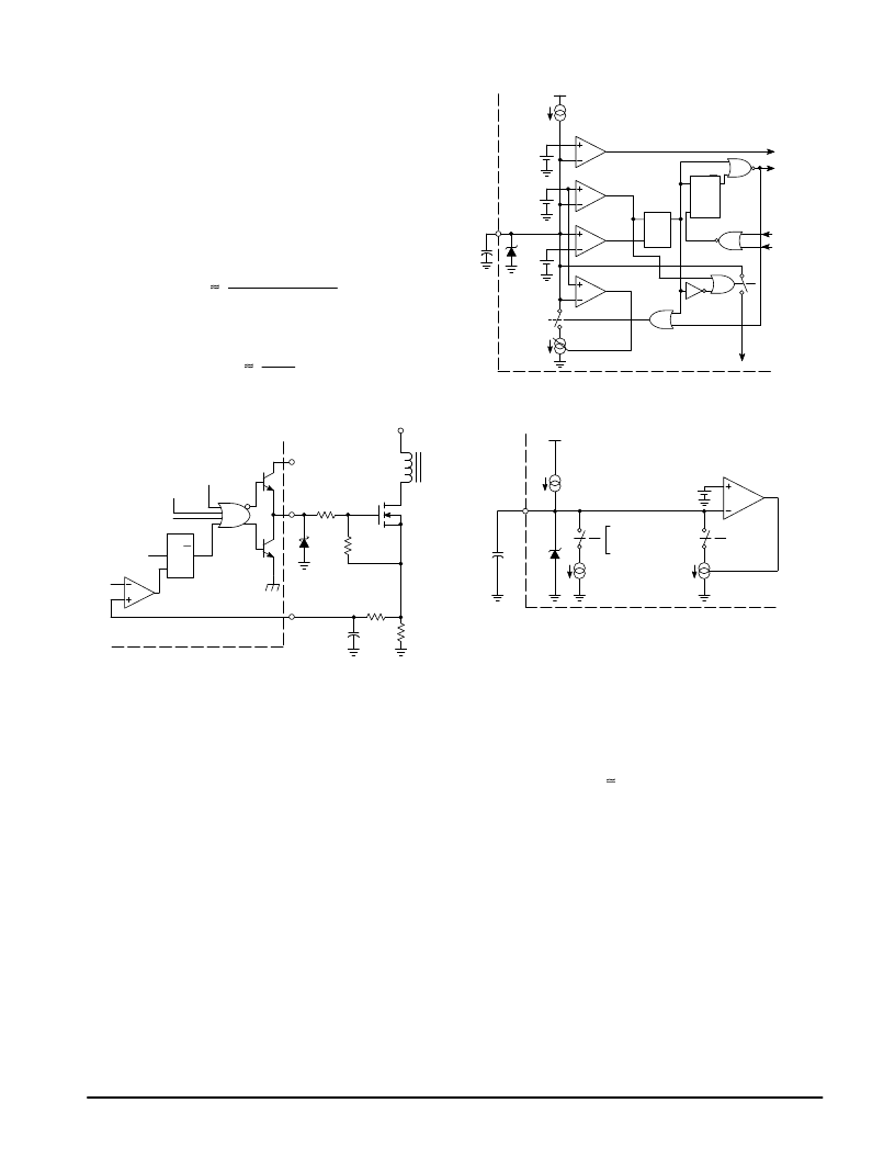
Figure 33. Output Totem Pole
R
PWM
Latch
R
S
Q
UVLO
VOSC prot
VDemag Out
Thermal
Protection
Current Sense
Comparator
Substrate
Current
Sense
14
3
7
C
RS
R
R3
Q1
Vin
VC
R2
1N5819
D
Series gate resistor, R2, will dampen any high frequency oscillations caused by
the MOSFET input capacitance and any series wiring inductance in the
gate–source circuit. Diode D is required if the negative current into the output
drive pin exceeds 15 mA.
Oscillator
The oscillator is a very accurate sawtooth generator that
can work either in free mode or in synchronization mode. In
this second mode, the oscillator stops in the low state and
waits for a demagnetization or a synchronization pulse to
start a new charging cycle.
The Sawtooth Generation:
In the steady state, the oscillator voltage varies between
about 1.6 V and 3.6 V.
The sawtooth is obtained by charging and discharging an
external capacitor CT (Pin 10), using two distinct current
sources = Icharge and Idischarge. In fact, CT is permanently
connected to the charging current source (0.4 Iref) and so,
the discharge current source has to be higher than the
charge current to be able to decrease the CT voltage (refer
to Figure 35).
This condition is performed, its value being (2.0 Iref) in
normal working and (0.4 Iref + 0.5 IF Stby in standby mode).
Figure 34. Oscillator
10
CT
1.0 V
1.6 V
3.6 V
Vref
0.4 Iref
CVOS prot
COSC Low
COSC High
COSC Regul
Synchro
1
0
IRegul
R
Disch
S
Q
CT < 1.6 V
Discharge
VOSC prot
R
LOSC
S
Q
VOSC
VDemag
Out
0
1
IDischarge
Figure 35. Simplified Block Oscillator
Vref
CT
10
ICharge
0.4 Iref
0
1
0: Discharge Phase
1: Charge Phase
COSC Regul
IRegul
1.6 V
IDischarge
Two comparators are used to generate the sawtooth. They
compare the CT voltage to the oscillator valley (1.6 V) and
peak reference (3.6 V) values. A latch (Ldisch) memorizes the
oscillator state.
In addition to the charge and discharge cycles, a third
state can exist. This phase can be produced when, at the end
of the discharge phase, the oscillator has to wait for a
synchronization or demagnetization pulse before restarting.
During this delay, the CT voltage must remain equal to the
oscillator valley value (
1.6 V). So, a third regulated current
source IRegul controlled by COSC Regul, is connected to CT n
order to perfectly compensate the (0.4 Iref) current source
that permanently supplies CT.
The maximum duty cycle is 80%. Indeed, the on–time is
allowed only during the oscillator capacitor charge.
Consequently:
Tcharge = CT x
V/Icharge
Tdischarge = CT x
V/Idischarge
where:
Tcharge is the oscillator charge time
V is the oscillator peak–to–peak value
Icharge is the oscillator charge current
and
Tdischarge is the oscillator discharge time
Idischarge is the oscillator discharge current
相关PDF资料 |
PDF描述 |
|---|---|
| MC44603AP | RV Series - Econoline Unregulated DC-DC Converters; Input Voltage (Vdc): 3.3V; Output Voltage (Vdc): 24V; Power: 2W; High Isolation 2W Converter; Approved for Medical Applications; EN and UL Safety Certificates; 6kVDC Isolation; Skinny DIP24 Package; Optional Continuous Short Circuit Protected; Fully Encapsulated; Very Low Isolation Capacitance |
| MC44603DW | RV Series - Econoline Unregulated DC-DC Converters; Input Voltage (Vdc): 3.3V; Output Voltage (Vdc): 24V; Power: 2W; High Isolation 2W Converter; Approved for Medical Applications; EN and UL Safety Certificates; 6kVDC Isolation; Skinny DIP24 Package; Optional Continuous Short Circuit Protected; Fully Encapsulated; Very Low Isolation Capacitance |
| MC44603P | RV Series - Econoline Unregulated DC-DC Converters; Input Voltage (Vdc): 3.3V; Output Voltage (Vdc): 3.3V; Power: 2W; High Isolation 2W Converter; Approved for Medical Applications; EN and UL Safety Certificates; 6kVDC Isolation; Skinny DIP24 Package; Optional Continuous Short Circuit Protected; Fully Encapsulated; Very Low Isolation Capacitance |
| MC44604P | HIGH SAFETY STANDBY LADDER MODE GREENLINE PWM CONTROLLER |
| MC44605P | HIGH SAFETY LATCHED MODE GREENLINE PWM CONTROLLER FOR (MULTI)SYNCHRONIZED APPLICATIONS |
相关代理商/技术参数 |
参数描述 |
|---|---|
| MC44603PG | 功能描述:电流型 PWM 控制器 Voltage/Current PWM w/Bust Mode Standby RoHS:否 制造商:Texas Instruments 开关频率:27 KHz 上升时间: 下降时间: 工作电源电压:6 V to 15 V 工作电源电流:1.5 mA 输出端数量:1 最大工作温度:+ 105 C 安装风格:SMD/SMT 封装 / 箱体:TSSOP-14 |
| MC44604 | 制造商:Rochester Electronics LLC 功能描述:- Bulk |
| MC44604_05 | 制造商:ONSEMI 制造商全称:ON Semiconductor 功能描述:High Safety Pulsed Mode Standby GreenLine TM PWM Controller |
| MC44604P | 功能描述:电流型 PWM 控制器 Voltage Mode PWM RoHS:否 制造商:Texas Instruments 开关频率:27 KHz 上升时间: 下降时间: 工作电源电压:6 V to 15 V 工作电源电流:1.5 mA 输出端数量:1 最大工作温度:+ 105 C 安装风格:SMD/SMT 封装 / 箱体:TSSOP-14 |
| MC44604PG | 功能描述:电流型 PWM 控制器 Voltage Mode PWM w/Bust Mode Standby RoHS:否 制造商:Texas Instruments 开关频率:27 KHz 上升时间: 下降时间: 工作电源电压:6 V to 15 V 工作电源电流:1.5 mA 输出端数量:1 最大工作温度:+ 105 C 安装风格:SMD/SMT 封装 / 箱体:TSSOP-14 |
发布紧急采购,3分钟左右您将得到回复。