- 您现在的位置:买卖IC网 > PDF目录2094 > MC44BC375UAFCR2 (Freescale Semiconductor)IC MODULATOR AUD/VID VHF 20-QFN PDF资料下载
参数资料
| 型号: | MC44BC375UAFCR2 |
| 厂商: | Freescale Semiconductor |
| 文件页数: | 3/16页 |
| 文件大小: | 0K |
| 描述: | IC MODULATOR AUD/VID VHF 20-QFN |
| 标准包装: | 2,500 |
| 类型: | 调制器 |
| 应用: | 机顶盒 |
| 安装类型: | 表面贴装 |
| 封装/外壳: | 20-VFQFN 裸露焊盘 |
| 供应商设备封装: | 20-QFN 裸露焊盘(4x4) |
| 包装: | 带卷 (TR) |
Application Specific Products
Freescale Semiconductor
11
MC44BC375U
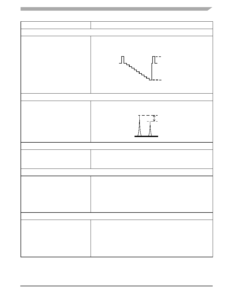
Video Modulation Depth
No audio signal
Video: 10 step grey scale
This is measured using a HP8596E Spectrum Analyzer with a TV Trigger option,
allowing demodulation and triggering on any specified TV Line. The analyzer is
centered on the maximum peak of the Video signal and reduced to zero Hertz
span in Linear mode to demodulate the Video carrier.
The Modulation Depth is calculated as (A-B)/A x 100 in%.
Picture to Sound Ratio
No video signal
No audio Signal
“PSS” pin set Low and High
Measure in dBc sound carrier in reference to picture carrier (RFout_Ref) for
“PSS” = Low (PS = 14 dB typical) and for “PSS” = High (PS = 16 dB),
Audio Modulation Depth — FM Modulation
Video Black Level
Audio signal: 1.0 KHz, 205 mVrms.
This is measured using a Demodulator in B/G
and an Audio Analyzer at 1.0 KHz.
The audio signal 205 mV at 1.0 KHz is supplied by the Audio Analyzer, and the
FM demodulated signal deviation is indicated on the Demodulator in KHz peak.
This value is then converted in% of FM deviation, based on specified standards.
Audio Frequency Response
Video Black Level
Audio signal: 50 Hz to 15 KHz, 100 mVrms
This is measured using a Demodulator in B/G
and an Audio Analyzer.
The audio signal 1.0 KHz 100 mVrms is supplied by the Audio Analyzer,
demodulated by the Demodulator and the audio analyzer measures the AC
amplitude of this demodulated audio signal: this value is taken as a reference
(0 dB).
The audio signal is then swept from 50 Hz to 15 KHz, and demodulated AC
amplitude is measured in dB relative to the 1.0 KHz reference.
Audio pre-emphasis and de-emphasis circuits are engaged, all audio analyzer
filters are switched OFF.
Audio Distortion FM
Audio: 1.0 KHz, adjustable level
Video Black Level
This is measured using a Demodulator in B/G
and an Audio Analyzer at 1.0 KHz. The output
level of the Audio analyzer is varied to obtain
a deviation of 50 KHz indicated on the
Demodulator.
The input rms detector of the Audio Analyzer converts the ac level of the
combined signal + noise + distortion to dc. It then removes the fundamental
signal (1.0 KHz) after having measured the frequency. The output rms detector
converts the residual noise + distortion to dc. The dc voltmeter measures both
dc signals and calculates the ratio in% of the two signals.
Table 9. Performance Measurement Test Set-Ups (continued)
Device and Signals Set-Up
Measurement Set-Up
A ( 6-10mV)
B (0.6 - 3mV)
TV Line Demodulated by Spectrum Analyzer-BG standard
A(mV)
B(mV)
Picture carrier
Sound carrier
+5.5 MHz
Fo
ADist
Distorsion
Noise
+
() Distorsion Noise Signal
++
()
=
相关PDF资料 |
PDF描述 |
|---|---|
| MC74ACT00N | IC GATE NAND QUAD 2INPUT 14-DIP |
| MC74ACT02N | IC GATE NOR QUAD 2INPUT 14-DIP |
| MC74ACT04MG | IC INVERTER HEX TTL 14-SOEIAJ |
| MC74ACT05N | IC INVERTER HEX OPN DRN 14-DIP |
| MC74ACT08DTR2 | IC GATE AND QUAD 2INPUT 14-TSSOP |
相关代理商/技术参数 |
参数描述 |
|---|---|
| MC44BC375UD | 制造商:MOTOROLA 制造商全称:Motorola, Inc 功能描述:PLL Tuned VHF Audio/ Video High Integration Modulator ICs |
| MC44BC375UEF | 功能描述:IC A-VHF MODULATOR 16-SOIC RoHS:是 类别:集成电路 (IC) >> 线性 - 视频处理 系列:- 产品变化通告:Product Discontinuation 07/Mar/2011 标准包装:3,000 系列:OMNITUNE™ 类型:调谐器 应用:移动电话,手机,视频显示器 安装类型:表面贴装 封装/外壳:65-WFBGA 供应商设备封装:PG-WFSGA-65 包装:带卷 (TR) 其它名称:SP000365064 |
| MC44BC375UEFR2 | 功能描述:IC A-VHF MODULATOR 16-SOIC RoHS:是 类别:集成电路 (IC) >> 线性 - 视频处理 系列:- 产品变化通告:Product Discontinuation 07/Mar/2011 标准包装:3,000 系列:OMNITUNE™ 类型:调谐器 应用:移动电话,手机,视频显示器 安装类型:表面贴装 封装/外壳:65-WFBGA 供应商设备封装:PG-WFSGA-65 包装:带卷 (TR) 其它名称:SP000365064 |
| MC44BC375VAEFR2 | 制造商:Freescale Semiconductor 功能描述: |
| MC44BC380 | 制造商:MOTOROLA 制造商全称:Motorola, Inc 功能描述:VHF/ UHF ANTENNA BOOSTER/SPLITTER IC |
发布紧急采购,3分钟左右您将得到回复。