- 您现在的位置:买卖IC网 > PDF目录11981 > MC68HC705P6AMDW (Freescale Semiconductor)IC MCU 4.6K OTP 2.1MHZ 28-SOIC PDF资料下载
参数资料
| 型号: | MC68HC705P6AMDW |
| 厂商: | Freescale Semiconductor |
| 文件页数: | 51/98页 |
| 文件大小: | 0K |
| 描述: | IC MCU 4.6K OTP 2.1MHZ 28-SOIC |
| 标准包装: | 26 |
| 系列: | HC05 |
| 核心处理器: | HC05 |
| 芯体尺寸: | 8-位 |
| 速度: | 2.1MHz |
| 连通性: | SIO |
| 外围设备: | POR,WDT |
| 输入/输出数: | 21 |
| 程序存储器容量: | 4.5KB(4.5K x 8) |
| 程序存储器类型: | OTP |
| RAM 容量: | 176 x 8 |
| 电压 - 电源 (Vcc/Vdd): | 3 V ~ 5.5 V |
| 数据转换器: | A/D 4x8b |
| 振荡器型: | 内部 |
| 工作温度: | -40°C ~ 125°C |
| 封装/外壳: | 28-SOIC(0.295",7.50mm 宽) |
| 包装: | 管件 |
第1页第2页第3页第4页第5页第6页第7页第8页第9页第10页第11页第12页第13页第14页第15页第16页第17页第18页第19页第20页第21页第22页第23页第24页第25页第26页第27页第28页第29页第30页第31页第32页第33页第34页第35页第36页第37页第38页第39页第40页第41页第42页第43页第44页第45页第46页第47页第48页第49页第50页当前第51页第52页第53页第54页第55页第56页第57页第58页第59页第60页第61页第62页第63页第64页第65页第66页第67页第68页第69页第70页第71页第72页第73页第74页第75页第76页第77页第78页第79页第80页第81页第82页第83页第84页第85页第86页第87页第88页第89页第90页第91页第92页第93页第94页第95页第96页第97页第98页
A/D Conversion Data Register (ADC)
MC68HC705P6A Advance Information Data Sheet, Rev. 2.1
Freescale Semiconductor
55
ADRC — RC Oscillator Control
When ADRC is set, the A/D subsystem operates from the internal RC oscillator instead of the internal
clock. The RC oscillator requires a time, tRCON, to stabilize before accurate conversion results can be
obtained. See 9.2.2 Reference Voltage (VREFH) for more information.
ADON — A/D Subsystem On
When the A/D subsystem is turned on (ADON = 1), it requires a time, tADON, to stabilize before
accurate conversion results can be attained.
CH2–CH0 — Channel Select Bits
CH2, CH1, and CH0 form a 3-bit field which is used to select an input to the A/D converter. Channels
0–3 correspond to port C input pins PC6–PC3. Channels 4–6 are used for reference measurements.
Channel 7 is reserved. If a conversion is attempted with channel 7 selected, the result will be $00.
Table 9-1 lists the inputs selected by bits CH0-CH3.
If the ADON bit is set and an input from channels 0–4 is selected, the corresponding port C pin’s DDR
bit will be cleared (making that port C pin an input). If the port C data register is read while the A/D is
on and one of the shared input channels is selected using bit CH0–CH2, the corresponding port C pin
will read as a logic 0. The remaining port C pins will read normally. To digitally read a port C pin, the
A/D subsystem must be disabled (ADON = 0), or input channels 5–7 must be selected.
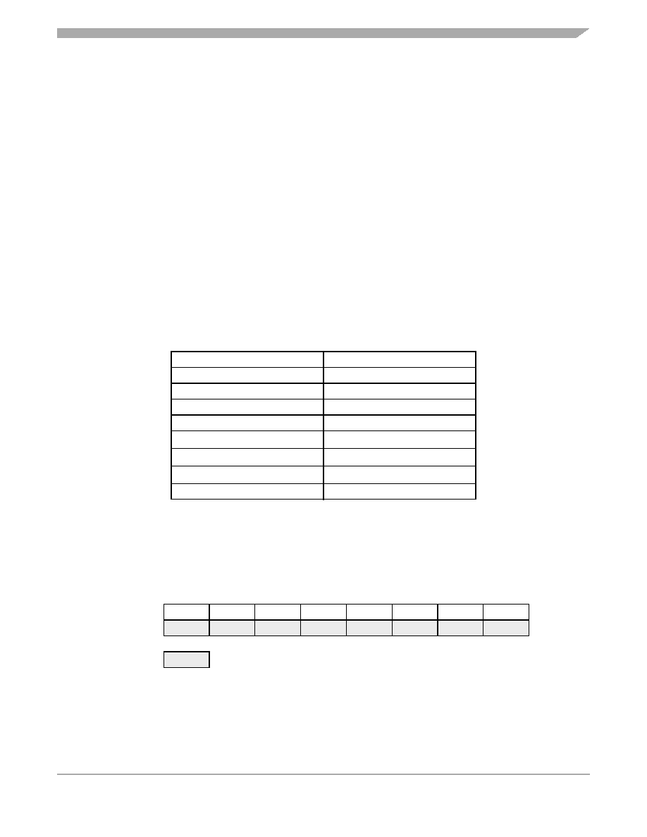
9.6 A/D Conversion Data Register (ADC)
This register contains the output of the A/D converter. See Figure 9-2.
Table 9-1. A/D Multiplexer Input Channel Assignments
Channel
Signal
0
AD0 — port C, bit 6
1
AD1 — port C, bit 5
2
AD2 — port C, bit 4
3
AD3 — port C, bit 3
4
VREFH — port C, bit 7
5
(VREFH + VSS)/2
6
VSS
7
Reserved for factory test
Address: $001D
Bit 7
654321
Bit 0
Read:
AD7
AD6
AD5
AD4
AD3
AD2
AD1
AD0
Write:
Reset:
Unaffected by reset
= Unimplemented
Figure 9-2. A/D Conversion Value Data Register (ADC)
相关PDF资料 |
PDF描述 |
|---|---|
| VI-JTJ-IX | CONVERTER MOD DC/DC 36V 75W |
| VI-24Z-IW-F3 | CONVERTER MOD DC/DC 2V 40W |
| VI-J54-IX | CONVERTER MOD DC/DC 48V 75W |
| MC68HC705C8AB | IC MCU 8K OTP 2.1MHZ 42-SDIP |
| VI-JTF-IX | CONVERTER MOD DC/DC 72V 75W |
相关代理商/技术参数 |
参数描述 |
|---|---|
| MC68HC705P6AMP | 制造商:Rochester Electronics LLC 功能描述:- Bulk |
| MC68HC705P6CDW | 制造商:Motorola Inc 功能描述: |
| MC68HC705P6CP | 制造商:Freescale Semiconductor 功能描述: 制造商:Motorola Inc 功能描述: |
| MC68HC705P6ECDW | 制造商:Motorola Inc 功能描述: 制造商:MOTOROLA 功能描述: |
| MC68HC705SR3CP | 功能描述:IC MCU 3.75K 2.1MHZ OTP 40-DIP RoHS:否 类别:集成电路 (IC) >> 嵌入式 - 微控制器, 系列:HC05 其它有关文件:STM32F101T8 View All Specifications 特色产品:STM32 32-bit Cortex MCUs 标准包装:490 系列:STM32 F1 核心处理器:ARM? Cortex?-M3 芯体尺寸:32-位 速度:36MHz 连通性:I²C,IrDA,LIN,SPI,UART/USART 外围设备:DMA,PDR,POR,PVD,PWM,温度传感器,WDT 输入/输出数:26 程序存储器容量:64KB(64K x 8) 程序存储器类型:闪存 EEPROM 大小:- RAM 容量:10K x 8 电压 - 电源 (Vcc/Vdd):2 V ~ 3.6 V 数据转换器:A/D 10x12b 振荡器型:内部 工作温度:-40°C ~ 85°C 封装/外壳:36-VFQFN,36-VFQFPN 包装:托盘 配用:497-10030-ND - STARTER KIT FOR STM32497-8853-ND - BOARD DEMO STM32 UNIV USB-UUSCIKSDKSTM32-PL-ND - KIT IAR KICKSTART STM32 CORTEXM3497-8512-ND - KIT STARTER FOR STM32F10XE MCU497-8505-ND - KIT STARTER FOR STM32F10XE MCU497-8304-ND - KIT STM32 MOTOR DRIVER BLDC497-6438-ND - BOARD EVALUTION FOR STM32 512K497-6289-ND - KIT PERFORMANCE STICK FOR STM32MCBSTM32UME-ND - BOARD EVAL MCBSTM32 + ULINK-MEMCBSTM32U-ND - BOARD EVAL MCBSTM32 + ULINK2更多... 其它名称:497-9032STM32F101T8U6-ND |
发布紧急采购,3分钟左右您将得到回复。