参数资料
| 型号: | MC74LCXU04MG |
| 厂商: | ON Semiconductor |
| 文件页数: | 4/8页 |
| 文件大小: | 0K |
| 描述: | IC INVERTER UNBUFF HEX 14-SOEIAJ |
| 产品变化通告: | Product Discontinuation 30/Sept/2011 |
| 标准包装: | 50 |
| 系列: | 74LCX |
| 逻辑类型: | 反相器 |
| 电路数: | 6 |
| 输入数: | 1 |
| 电源电压: | 2 V ~ 3.6 V |
| 电流 - 静态(最大值): | 10µA |
| 输出电流高,低: | 18mA,16mA |
| 逻辑电平 - 低: | 0.55V |
| 逻辑电平 - 高: | 1.7 V ~ 2.7 V |
| 额定电压和最大 CL 时的最大传播延迟: | 3.6ns @ 3V ~ 3.6V,50pF |
| 工作温度: | -40°C ~ 85°C |
| 安装类型: | 表面贴装 |
| 供应商设备封装: | SOEIAJ-14 |
| 封装/外壳: | 14-SOIC(0.209",5.30mm 宽) |
| 包装: | 管件 |
MC74LCXU04
http://onsemi.com
4
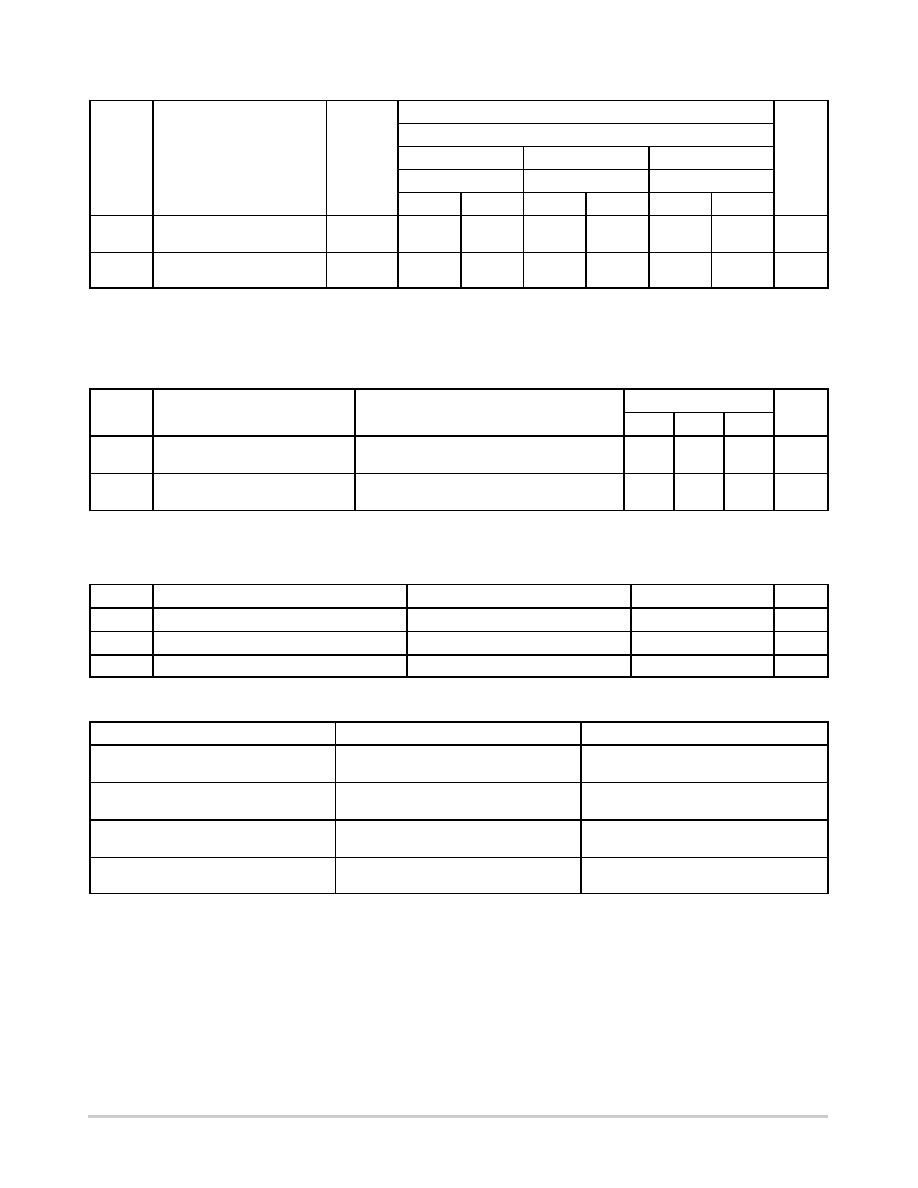
Symbol
Parameter
Waveform
Limits
Units
TA = 40°C to +85°C
VCC = 3.3 V ± 0.3 V
VCC = 2.7 V
VCC = 2.5 V ± 0.2 V
CL = 50 pF
CL = 30 pF
Min
Max
Min
Max
Min
Max
tPLH
tPHL
Propagation Delay
Input to Output
1
1.0
3.6
1.0
4.5
1.0
4.3
ns
tOSHL
tOSLH
OutputtoOutput Skew
(Note 4)
1.0
ns
3. These AC parameters are preliminary and may be modified.
4. Skew is defined as the absolute value of the difference between the actual propagation delay for any two separate outputs of the same device.
The specification applies to any outputs switching in the same direction, either HIGHtoLOW (tOSHL) or LOWtoHIGH (tOSLH); parameter
guaranteed by design.
DYNAMIC SWITCHING CHARACTERISTICS
TA = +25°C
Symbol
Characteristic
Condition
Min
Typ
Max
Units
VOLP
Dynamic LOW Peak Voltage
(Note 5)
VCC = 3.3 V, CL = 50 pF, VIH = 3.3 V, VIL = 0 V
VCC = 2.5 V, CL = 30 pF, VIH = 2.5 V, VIL = 0 V
0.8
0.6
V
VOLV
Dynamic LOW Valley Voltage
(Note 5)
VCC = 3.3 V, CL = 50 pF, VIH = 3.3 V, VIL = 0 V
VCC = 2.5 V, CL = 30 pF, VIH = 2.5 V, VIL = 0 V
0.8
0.6
V
5. Number of outputs defined as “n”. Measured with “n1” outputs switching from HIGHtoLOW or LOWtoHIGH. The remaining output is
measured in the LOW state.
CAPACITIVE CHARACTERISTICS
Symbol
Parameter
Condition
Typical
Units
CIN
Input Capacitance
VCC = 3.3 V, VI = 0 V or VCC
7
pF
COUT
Output Capacitance
VCC = 3.3 V, VI = 0 V or VCC
8
pF
CPD
Power Dissipation Capacitance
10 MHz, VCC = 3.3 V, VI = 0 V or VCC
25
pF
ORDERING INFORMATION
Device
Package
Shipping
MC74LCXU04DG
SOIC14
(PbFree)
55 Units / Rail
MC74LCXU04DR2G
SOIC14
(PbFree)
2500 Tape & Reel
MC74LCXU04DTG
TSSOP14
(PbFree)
96 Units / Rail
MC74LCXU04DTR2G
TSSOP14
(PbFree)
2500 Tape & Reel
For information on tape and reel specifications, including part orientation and tape sizes, please refer to our Tape and Reel Packaging
Specifications Brochure, BRD8011/D.
相关PDF资料 |
PDF描述 |
|---|---|
| MC74LVX00MG | IC GATE NAND QUAD 2INP 14-SOEIAJ |
| MC74LVX02MG | IC GATE NOR QUAD 2INPUT 14SOEIAJ |
| MC74LVX04MG | IC INVERTER HEX ADV HS 14-SOEIAJ |
| MC74LVX08MG | IC GATE AND QUAD 2INPUT 14SOEIAJ |
| MC74LVX132MG | IC SCHMITT TRIGGER NAND 14SOEIAJ |
相关代理商/技术参数 |
参数描述 |
|---|---|
| MC74LS04D | 制造商:Motorola Inc 功能描述: |
| MC74LS125D | 制造商:Motorola 功能描述:74LS125 MOT IN S3E8A |
| MC74LS132N | 制造商:Motorola Inc 功能描述: |
| MC74LS139D | 制造商:Motorola Inc 功能描述: |
| MC74LS156 | 制造商:n/a 功能描述:74LS156 MOT |
发布紧急采购,3分钟左右您将得到回复。