参数资料
| 型号: | MC75172BDWG |
| 厂商: | ON Semiconductor |
| 文件页数: | 13/13页 |
| 文件大小: | 0K |
| 描述: | IC LINEDRIVER QUAD 3ST 20-SOICW |
| 产品变化通告: | Product Obsolescence 24/Jan/2011 |
| 标准包装: | 38 |
| 类型: | 线路驱动器,发射器 |
| 驱动器/接收器数: | 4/0 |
| 规程: | RS422,RS485 |
| 电源电压: | 4.75 V ~ 5.25 V |
| 安装类型: | 表面贴装 |
| 封装/外壳: | 20-SOIC(0.295",7.50mm 宽) |
| 供应商设备封装: | 20-SOIC |
| 包装: | 管件 |
MC75172B, MC75174B
http://onsemi.com
9
The
maximum
ambient
operating
temperature
(applicable to both EIA485 and EIA422A) is listed as
85
°C. However, a lower ambient may be required
depending on system use (i.e. specifically how many
drivers within a package are used) and at what current
levels they are operating. The maximum power which may
be dissipated within the package is determined by:
PDmax +
T
Jmax
–T
A
RqJA
RqJA = package thermal resistance (typical
70
°C/W for the DIP package, 85°C/W for
SOIC package);
TJmax = max. operating junction
temperature, and
TA = ambient temperature.
where:
Since the thermal shutdown feature has a trip point of
150
°C, ±20°C, TJmax is selected to be 130°C. The power
dissipated within the package is calculated from:
= {[(VCC VOH)
IOH] + VOL IOL)} each
driver = + (VCC
ICC)
VCC = the supply voltage;
VOH, VOL are measured or estimated from
Figures 7 to 10;
ICC = the quiescent power supply current
(typical 60 mA).
PD
where:
As indicated in the equation, the first term (in brackets)
must be calculated and summed for each of the four drivers,
while the last term is common to the entire package.
Example 1: TA = 25
°C, IOL = IOH = 55 mA for each
driver, VCC = 5.0 V, DIP package. How many drivers per
package can be used?
Maximum allowable power dissipation is:
PDmax +
130
°C * 25°C
70
°C W
+ 1.5 W
Since the power supply current of 60 mA dissipates
300 mW, that leaves 1.2 W (1.5 W 0.3 W) for the drivers.
From Figures 7 and 9, VOL
[1.75 V, and VOH [3.85 V.
The power dissipated in each driver is:
{(5.0 3.85)
0.055} + (1.75 0.055) = 160 mW.
Since each driver dissipates 160 mW, the four drivers per
package could be used in this application.
Example 2: TA = 85
°C, IOL = 27.8 mA, IOH = 20 mA for
each driver, VCC =5.0 V, SOIC package. How many drivers
per package can be used?
Maximum allowable power dissipation is:
PDmax +
130
°C * 85°C
85
°C W
+ 0.53 W
Since the power supply current of 60 mA dissipates
300 mW, that leaves 230 mW (530 mW 300 mW) for the
drivers. From Figures 8 and 10 (adjusted for VCC = 5.0 V),
VOL
[1.38 V, and VOH [4.27 V. The power dissipated
in each driver is:
{(5.0 4.27)
0.020} + (1.38 0.0278) = 53 mW
Since each driver dissipates 53 mW, the use of all four
drivers in a package would be marginal. Options include
reducing
the
load
current,
reducing
the
ambient
temperature, and/or providing a heat sink.
System Requirements
EIA485 requires each driver to be capable of
transmitting data differentially to at least 32 unit loads, plus
an equivalent DC termination resistance of 60
W, over a
common mode voltage of 7.0 to 12 V. A unit load (U.L.),
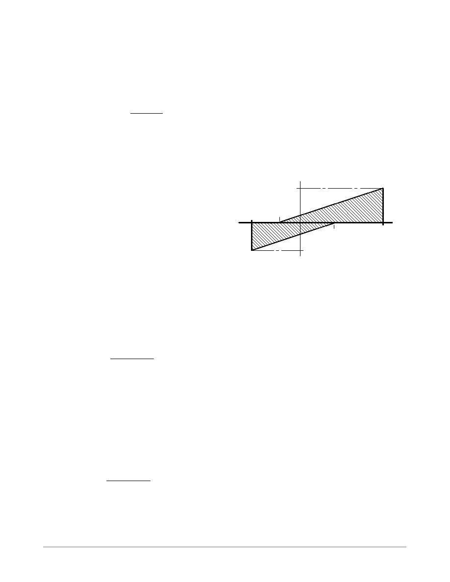
as defined by EIA485, is shown in Figure 17.
Figure 17. Unit Load Definition
1.0 mA
V
5.0 V
3.0 V
7.0 V
12 V
0.8 mA
Reprinted from EIA485, Electronic Industries Association,
Washington,DC.
I
A load current within the shaded regions represents an
impedance of less than one U.L., while a load current of a
magnitude outside the shaded area is greater than one U.L.
A system’s total load is the sum of the unit load equivalents
of each receiver’s input current, and each disabled driver’s
output leakage current. The 60
W termination resistance
mentioned above allows for two 120
W terminating
resistors.
Using the EIA485 requirements (worst case limits), and
the graphs of Figures 7 and 9, it can be determined that the
maximum current an MC75172B or MC75174B driver will
source or sink is
[65 mA.
System Example
An example of a typical EIA485 system is shown in
Figure 18. In this example, it is assumed each receiver’s
input characteristics correspond to 1.0 U.L. as defined in
Figure 17. Each “off” driver, with a maximum leakage of
±50 mA over the common mode range, presents a load of
[0.06 U.L. The total load for the active driver is therefore
8.3 unit loads, plus the parallel combination of the two
terminating resistors (60
W). It is up to the system software
to control the driver Enable pins to ensure that only one
driver is active at any time.
相关PDF资料 |
PDF描述 |
|---|---|
| VI-B3B-MW-S | CONVERTER MOD DC/DC 95V 100W |
| CY28446LFXCT | IC CLOCK CALISTOGA CK410M 64QFN |
| CY28445LFXC-5T | IC CLOCK CALISTOGA CK410M 68QFN |
| VI-B4J-IU | CONVERTER MOD DC/DC 36V 200W |
| MC1489DR2G | IC LINE RECEIVER QUAD 14-SOIC |
相关代理商/技术参数 |
参数描述 |
|---|---|
| MC75172BDWR2 | 功能描述:RS-485接口IC Quad EIA-485 Line RoHS:否 制造商:Texas Instruments 数据速率:250 Kbps 工作电源电压:3.3 V 电源电流:750 uA 工作温度范围:- 40 C to + 125 C 安装风格:SMD/SMT 封装 / 箱体:SOIC-8 封装:Tube |
| MC75172BDWR2G | 功能描述:RS-485接口IC Quad EIA-485 Line Driver w/3 State Out RoHS:否 制造商:Texas Instruments 数据速率:250 Kbps 工作电源电压:3.3 V 电源电流:750 uA 工作温度范围:- 40 C to + 125 C 安装风格:SMD/SMT 封装 / 箱体:SOIC-8 封装:Tube |
| MC75174 | 制造商:ONSEMI 制造商全称:ON Semiconductor 功能描述:QUAD EIA-485 LINE DRIVERS |
| MC75174B | 制造商:MOTOROLA 制造商全称:Motorola, Inc 功能描述:QUAD EIA-485 LINE DRIVERS WITH THREE-STATE OUTPUTS |
| MC75174BDW | 功能描述:RS-485接口IC Quad EIA-485 Line RoHS:否 制造商:Texas Instruments 数据速率:250 Kbps 工作电源电压:3.3 V 电源电流:750 uA 工作温度范围:- 40 C to + 125 C 安装风格:SMD/SMT 封装 / 箱体:SOIC-8 封装:Tube |
发布紧急采购,3分钟左右您将得到回复。