- 您现在的位置:买卖IC网 > Datasheet目录342 > MCB1114 (Keil)BOARD EVALUATION FOR NXP LPC1114 Datasheet资料下载
参数资料
| 型号: | MCB1114 |
| 厂商: | Keil |
| 文件页数: | 8/53页 |
| 文件大小: | 0K |
| 描述: | BOARD EVALUATION FOR NXP LPC1114 |
| 产品培训模块: | Code Density for LPC11xx |
| 标准包装: | 1 |
| 类型: | MCU |
| 适用于相关产品: | LPC1114 |
| 所含物品: | 板,线缆 |
第1页第2页第3页第4页第5页第6页第7页当前第8页第9页第10页第11页第12页第13页第14页第15页第16页第17页第18页第19页第20页第21页第22页第23页第24页第25页第26页第27页第28页第29页第30页第31页第32页第33页第34页第35页第36页第37页第38页第39页第40页第41页第42页第43页第44页第45页第46页第47页第48页第49页第50页第51页第52页第53页
�� �
�
�NXP� Semiconductors�
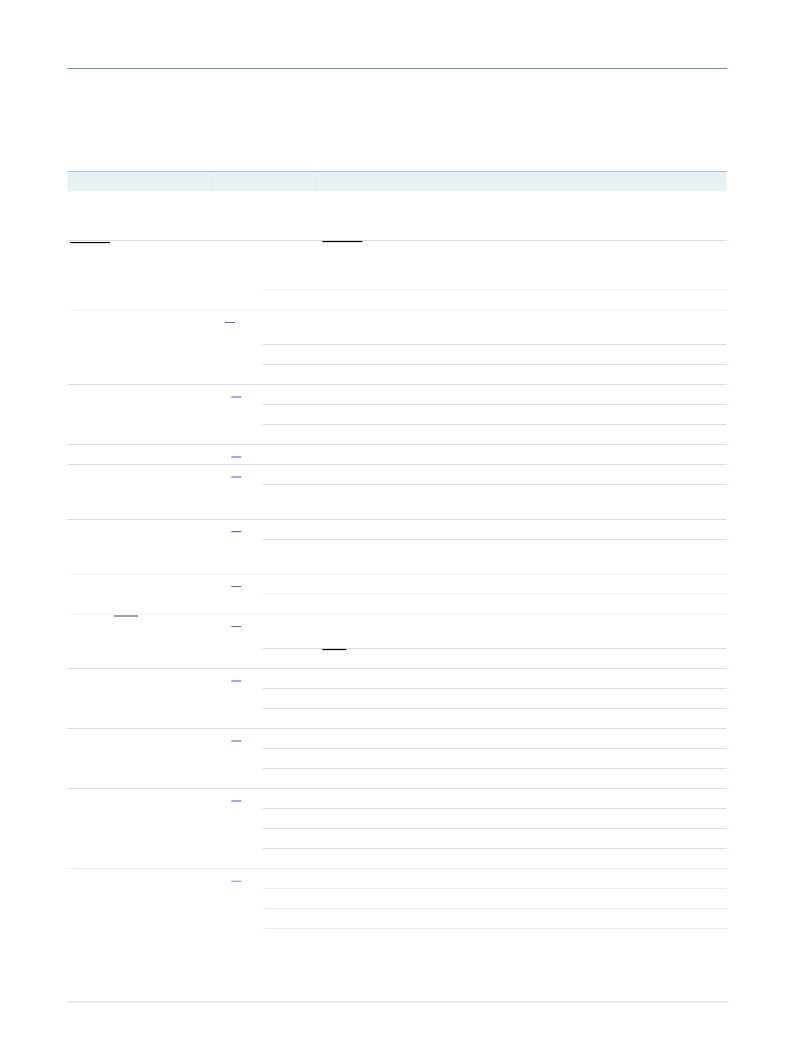
�6.2� Pin� description�
�LPC1111/12/13/14�
�Table� 3.�
�LPC1113/14� pin� description� table� (LQFP48� package)�
�Symbol�
�PIO0_0� to� PIO0_11�
�Pin�
�Type�
�I/O�
�Description�
�Port� 0� —� Port� 0� is� a� 12-bit� I/O� port� with� individual� direction� and� function�
�controls� for� each� bit.� The� operation� of� port� 0� pins� depends� on� the� function�
�selected� through� the� IOCONFIG� register� block.�
�RESET/PIO0_0�
�3�
�I�
�RESET� —� External� reset� input:� A� LOW� on� this� pin� resets� the� device,�
�causing� I/O� ports� and� peripherals� to� take� on� their� default� states,� and�
�processor� execution� to� begin� at� address� 0.�
�I/O�
�PIO0_0� —� General� purpose� digital� input/output� pin.�
�PIO0_1/CLKOUT/�
�4� [1]�
�I/O�
�PIO0_1� —� General� purpose� digital� input/output� pin.� A� LOW� level� on� this� pin�
�CT32B0_MAT2�
�O�
�O�
�during� reset� starts� the� ISP� command� handler.�
�CLKOUT� —� Clockout� pin.�
�CT32B0_MAT2� —� Match� output� 2� for� 32-bit� timer� 0.�
�PIO0_2/SSEL0/�
�CT16B0_CAP0�
�PIO0_3�
�PIO0_4/SCL�
�10� [1]�
�14� [1]�
�15� [2]�
�I/O�
�O�
�I�
�I/O�
�I/O�
�I/O�
�PIO0_2� —� General� purpose� digital� input/output� pin.�
�SSEL0� —� Slave� Select� for� SPI0.�
�CT16B0_CAP0� —� Capture� input� 0� for� 16-bit� timer� 0.�
�PIO0_3� —� General� purpose� digital� input/output� pin.�
�PIO0_4� —� General� purpose� digital� input/output� pin.�
�SCL� —� I� 2� C-bus� clock� input/output.� High-current� sink� only� if� I� 2� C� Fast-mode�
�Plus� is� selected� in� the� I/O� configuration� register.�
�PIO0_5/SDA�
�16� [2]�
�I/O�
�I/O�
�PIO0_5� —� General� purpose� digital� input/output� pin.�
�SDA� —� I� 2� C-bus� data� input/output.� High-current� sink� only� if� I� 2� C� Fast-mode�
�Plus� is� selected� in� the� I/O� configuration� register.�
�PIO0_6/SCK0�
�PIO0_7/CTS�
�22� [1]�
�23� [1]�
�I/O�
�I/O�
�I/O�
�PIO0_6� —� General� purpose� digital� input/output� pin.�
�SCK0� —� Serial� clock� for� SPI0.�
�PIO0_7� —� General� purpose� digital� input/output� pin� (high-current� output�
�driver).�
�I�
�CTS� —� Clear� To� Send� input� for� UART.�
�PIO0_8/MISO0/�
�CT16B0_MAT0�
�PIO0_9/MOSI0/�
�CT16B0_MAT1�
�SWCLK/PIO0_10/�
�SCK0/CT16B0_MAT2�
�TDI/PIO0_11/�
�AD0/CT32B0_MAT3�
�27� [1]�
�28� [1]�
�29� [1]�
�32� [3]�
�I/O�
�I/O�
�O�
�I/O�
�I/O�
�O�
�I�
�I/O�
�I/O�
�O�
�I�
�I/O�
�PIO0_8� —� General� purpose� digital� input/output� pin.�
�MISO0� —� Master� In� Slave� Out� for� SPI0.�
�CT16B0_MAT0� —� Match� output� 0� for� 16-bit� timer� 0.�
�PIO0_9� —� General� purpose� digital� input/output� pin.�
�MOSI0� —� Master� Out� Slave� In� for� SPI0.�
�CT16B0_MAT1� —� Match� output� 1� for� 16-bit� timer� 0.�
�SWCLK� —� Serial� wire� clock� and� test� clock� TCK� for� JTAG� interface.�
�PIO0_10� —� General� purpose� digital� input/output� pin.�
�SCK0� —� Serial� clock� for� SPI0.�
�CT16B0_MAT2� —� Match� output� 2� for� 16-bit� timer� 0.�
�TDI� —� Test� Data� In� for� JTAG� interface.�
�PIO0_11� —� General� purpose� digital� input/output� pin.�
�LPC1111_12_13_14_0�
�I�
�O�
�AD0� —� A/D� converter,� input� 0.�
�CT32B0_MAT3� —� Match� output� 3� for� 32-bit� timer� 0.�
�?� NXP� B.V.� 2009.� All� rights� reserved.�
�Objective� data� sheet�
�Rev.� 00.11� —� 13� November� 2009�
�8� of� 53�
�相关PDF资料 |
PDF描述 |
|---|---|
| MCB11C14 | BOARD EVAL FOR NXP LPC11C14 |
| MCB2470 | BOARD EVAL NXP LPC247X SERIES |
| MCBSTM32EXL | BOARD EVALUATION FOR STM32F103ZE |
| MCBTMPM330 | BOARD EVAL TOSHIBA TMPM330 SER |
| MCIMX25WPDKJ | KIT DEVELOPMENT WINCE IMX25 |
相关代理商/技术参数 |
参数描述 |
|---|---|
| MCB1114-ED | 制造商:ARM Ltd 功能描述:KEIL NXP LPC1114 EVAL BOARD |
| MCB1114U | 功能描述:开发板和工具包 - ARM EVAL BOARD FOR NXP LPC1114 + ULINK2 RoHS:否 制造商:Arduino 产品:Development Boards 工具用于评估:ATSAM3X8EA-AU 核心:ARM Cortex M3 接口类型:DAC, ICSP, JTAG, UART, USB 工作电源电压:3.3 V |
| MCB1114U-ED | 制造商:ARM Ltd 功能描述:KEIL NXP LPC1114 EVAL BOARD |
| MCB1114UME | 功能描述:开发板和工具包 - ARM EVAL BOARD FOR NXP LPC1114 + ULINK-ME RoHS:否 制造商:Arduino 产品:Development Boards 工具用于评估:ATSAM3X8EA-AU 核心:ARM Cortex M3 接口类型:DAC, ICSP, JTAG, UART, USB 工作电源电压:3.3 V |
| MCB1114UME-ED | 制造商:ARM Ltd 功能描述:KEIL NXP LPC1114 EVAL BOARD |
发布紧急采购,3分钟左右您将得到回复。